Update for the 242. The gauge cluster has been in and out of this car so many times I think I can do it blind folded. So I ordered some custom gauges (S60R style) from SpeedHut. It took them three tries to get the artwork "right" but I'm happy with how they turned out. I also went to New Vintage for an indicator strip. Nothing custom - just Off-The-Shelf stuff so some things you can get and some you can't.
This is the how-to...in case you're interested in having a working cluster with GPS speedometer and things that, you know, work.
One of my three clusters had to be sacrificed. First the gauges were broken out...it's one I've been using for parts for years.
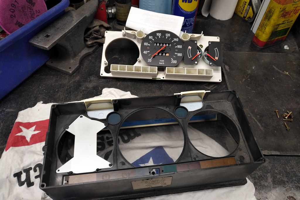
Cracked the front bezel off the main body.
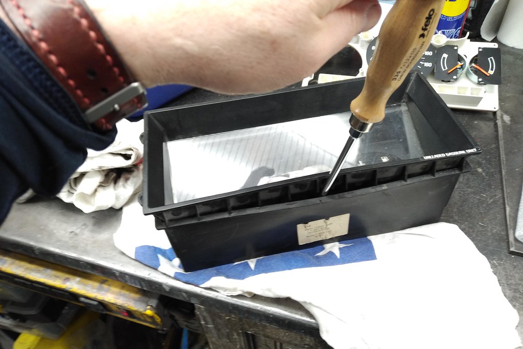
That works - if you're careful.

Quick test fit and marked the screw holes.

Marked and ready to cut. Sorry originality police - this one's a gonner.
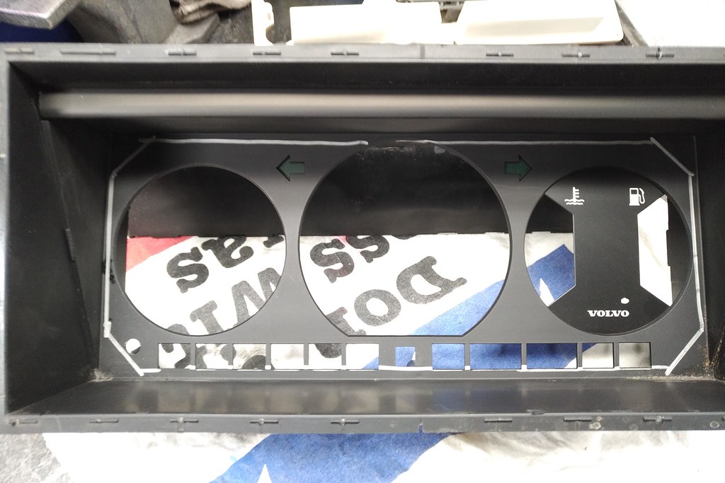
The little sawsall works a treat for this sort of careful surgery.

I JB Welded some rivnuts (M4 if you're still reading) into the corners.

Then started the gauge assembly. The SpeedHut gauges are actually very easy to wire up - the indicator strip...well, it's a little more of a pain.
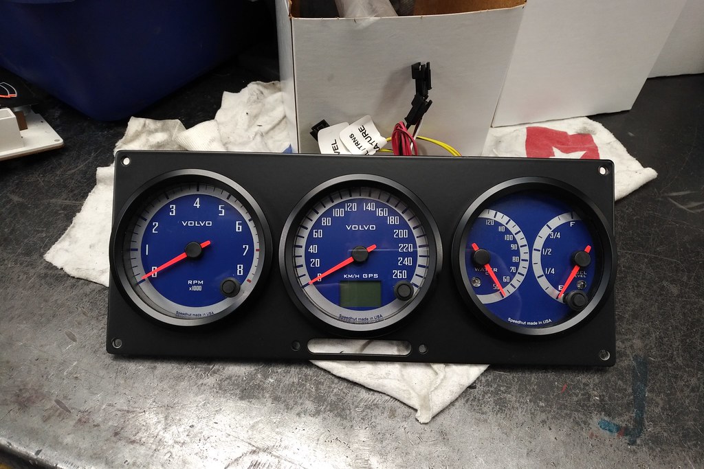
Here's the strip installed.

I didn't take any pictures of the wiring...it's just joining wires. Here's the brake down. The oil, parking brake (brake failure), bulb out, are all triggered by grounds. So join the positives on the LED's and put the grounds into their correct circuits. I stripped wire from a spare harness and used the same pin number for the plug (or as close as I could) - this will help any trouble shooting later. I also reused the fuel sender wiring but replaced the temperature sender wiring as the gauge came with a bespoke sender. The stock setting on the fuel gauge is the correct resistance (or close as anyone could care).
The turns, high beam are positive fed -so tie their grounds and look up the pin numbers. The last bit of fun was the alternator circuit. The alternator gets it's excitation (that's what makes is feel like working) from the gauge cluster. This messed me up for a while and Matt had to explain it really slowly

. I had wired it up correctly, but it didn't work.
The positive goes to switched power and the wire in the main cluster connector (it's red) goes to "ground" - it actually just goes to the alternator. So that makes the thing work until it's producing a voltage then the ground is replaced by positive and the light goes out.
The issue is that the LED draws so little current that it's not enough to make this circuit work. So you can either add a resistor (around 30 Ohms would do) or head on down to the parts store and pick up an indicator bulb (this is what I did - no patience and I wasn't going to go to my lab and get a resistor...I'm like that). Wire it in parallel with the LED - it's now a current limiting resistor. It works. You can't see it as it's wired on the inside of the dash. It should last for as long as I'll own this car.
Next up - how do these fancy Deutsch connectors work? Well they're awesome and they are in the DT series. I'm using them in my 122 build, so have a small fortune worth. I already had the solid barrel pin crimp tool (they're not cheap - they are essential). The DT's also can be had with a standard F-crimp style connector (the crimp that holds wire and jacketing). There is no place for solder in automotive wiring. There, I said it.
The barrel style crimp makes doing this installation possible from inside the car. It took me all of 45 minutes from start to testing. You can try to do this with the F-Crimp style, but it's a lot trickier and the crimp tools are bulky by comparison. They're also a little hard to handled when inside a dash.
The solid barrel style crimp with the right tool is a dream. Strip and prepare the wire.

Get the lengths just right. I have a special stripping tool for this job - it's for Tefzel wire, but works on everything. It won't put a single nick in the wires...and the dies are worth a lot more than the tool. I needed it for work - but I bought it for the future. It doesn't look different from the normal tool, but it is formed differently.
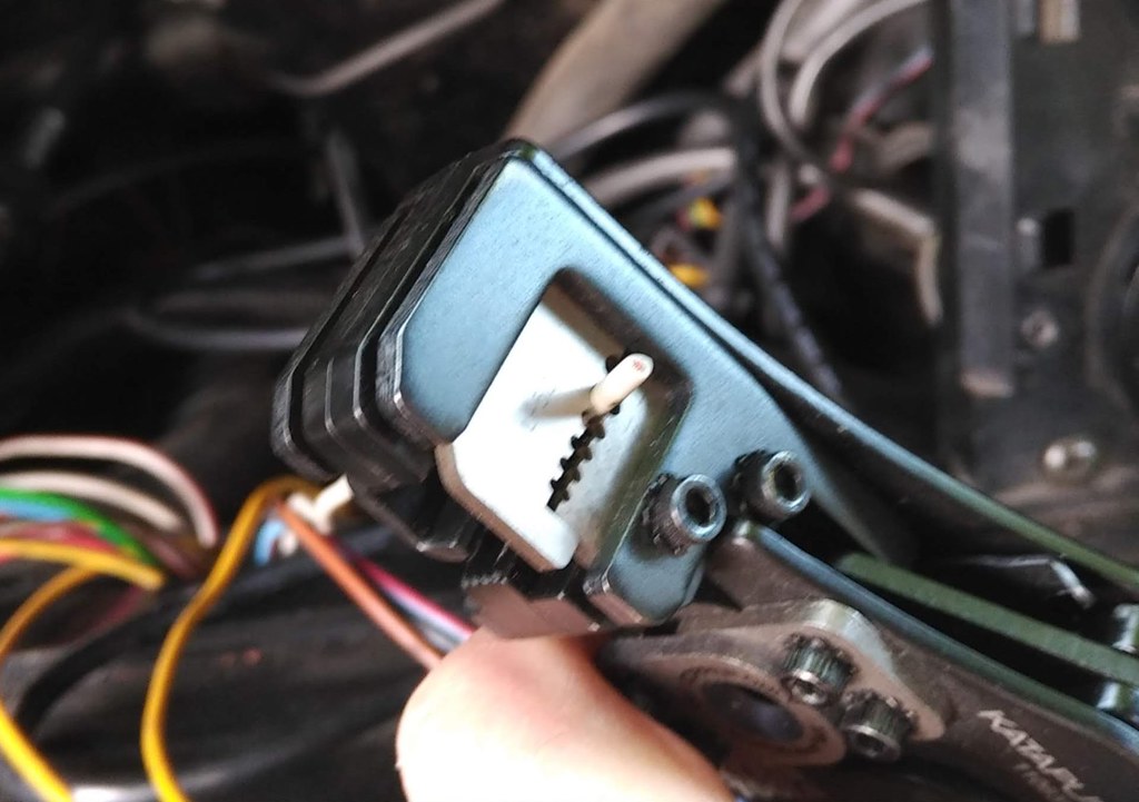
Check the fit - adjust length as needed. You're allowed a few thou worth of jacketing outside the crimp and the wire has to be seen in the inspection hole.
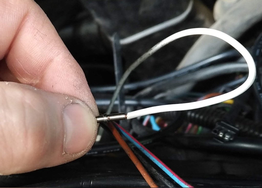
Drop the pin in the tool - insert wire. Be amazed.

This is what you're after - wire visible in the inspection hole, Jacketing just outside the pin and a nice firm crimp.

Insert in the back of the connector as per your wiring diagram and once it clicks in place you're done.

I taped up both sides of the harness with the correct harness tape.

Safely mount the GPS antenna in the unused speaker grille and you're ready to rock.

Nice and clean.

Indicator strip comes to life. I did double use the parking brake and brake failure...so if I'm driving and it comes on, that's a brake failure...if I'm parked - you get the logic.
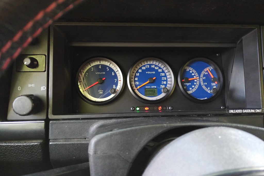
At night.

This all took a few days and a lot of time in the wiring diagram. It all works flawlessly. It also makes no noise while you drive. I'm happy with the result.

