hamburgler wrote:
I have now done the following checks (all while car is idling, no accessories):
-POS lead multimeter to POS alternator > NEG lead multimeter to POS starter = 0V
-POS lead multimeter to POS starter > NEG lead multimeter to POS battery = 0.9V (seems like a voltage drop)
-POS lead multimeter to POS starter > NEG lead multimeter to POS fuse box = 1.2V (even more of a voltage drop)
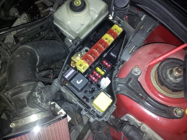
I have also noticed that my POS batter cable is extremely hot at the battery connection. I cannot touch it. It is also hot at the fuse box. I ran a separate battery wire from starter to batter and its now cool, but the fuse box POS is still very hot. Ill have to replace that too.
Local parts store tested the battery and its good but he said it just needs a charge so Im thinking alternator. It was 12.2V across the terminals.
Can someone tell me how many amps a Volvo alternator is supposed to put out?
1.2 volts is a lot of drain considering your accessory load and the short distance. Though you can live with some, I’d prefer to see closer to 0.2v total drop to that point.
Now that you’ve got the hang of testing, you need to verify that the voltage drop between the starter and battery has been reduced with the new cable. Then once you’re happy with the power the battery is getting, you can stop testing from the starter and start testing from the battery. See how much loss you’re getting between the battery and fuse box now – if it’s only 0.3v it’s not too bad, but I’m betting it’s more when you’re drawing full accessory load. Yes, these things can warm up with a lot of draw but they shouldn’t be too hot to touch. Check your battery ground to chassis using the same method – one lead of DVOM on battery NEG, the other to chassis and engine grounds. No distance is too small to test with this method, by the way. You can test the length of a wire, or from the wire to the ring/spade terminal that’s clamped to it, or from the terminal to the connection it makes with the next device. Battery clamp to battery terminal is another good place to lose some voltage, but you’ve cleaned them already so I don’t think that’s the problem in this case. I usually test between POS and NEG battery posts and then immediately between POS and NEG battery clamps, just as a routine check whenever I’m checking alternator output. A quick NEG to chassis and NEG to engine test follows, along with an alternator to battery POS test.
Be suspicious of every connection – between battery post and clamp, between battery clamp and wire, between one end of the wire and the other, between the other end of the wire and the ring terminal, between the ring terminal and the starter solenoid, etc. You can have a break or a bad connection at any of these points. Testing with an ohmmeter will test the resistance at each of these points, but on the higher current wires you may not see a significant loss by testing this way – you need to load it up and check the voltage loss. You can also use an infared temp gun if you can isolate the wire enough to be sure that it’s the only thing the gun is picking up, and if the loss is great enough.
Testing the battery is a waste if you’re getting good strong cold starts – the battery is only a buffer while the engine is running, generally accepting more amps than it discharges (recharging) while the engine is running. The alternator MAY have a blown rectifier circuit which will put out a certain amount of alternating current (that’s what the alternator naturally generates, but it uses a rectifier to create direct current and a regulator to … regulate it), but if that happens it’ll be at a much higher frequency than your eyes can detect as flickering in the lights. You can’t see a lightbulb flicker at 60 hz, and your alternator is spinning about 40-50 times per second and has at least 3 cycles per rotation, so more like 120-150 hz of flicker. I don’t believe the alternator is your problem either – it’s still jamming out the volts and amps, so I think you can rule it out for now. The typical mid-late ‘90s Volvo alternator puts out around 90 or 100 amps, by the way, while regulating at around 13.5-14 volts.
So the next tests I’d like to see are (both at idle and with full accessories):
ALT POS to BATT POS post – if voltage drop is more than 0.2v, break this test down at each connection.
BATT NEG post to a good clean chassis ground – if voltage drop is more than 0.2v, break it down.
BATT POS to fuse box (there may be a fuseable link in this line, which increases the drop slightly)
ALT POS to fuse box
Fuse box inlet to ignition switch main power
If you don’t find a loss of more than 0.1-0.2v at any of those tests and your dome lights are still dimming when you use power windows or heater fan, we are probably barking up the wrong tree. The headlights, TRACS, and obviously your engine are all running through your ignition switch, but your dome and glovebox lights are not. I’m pretty sure the ignition switch gets its power from the same place the battery ties into the fuse box, but I’m not sure what happens in the later cars with relays or whatever else might be happening to isolate things.