Change font size
It is currently Fri Apr 11, 2025 7:47 am


Post a new topicPost a reply Page 9 of 54   [ 801 posts ]
Go to page Previous  1 ... 6, 7, 8, 9, 10, 11, 12 ... 54  Next
Author Message
 Post subject:
PostPosted: Sun Nov 09, 2008 1:54 pm 
Haha, I just built a W24 Octo-Turbo, now what?!
User avatar

Joined: Wed Dec 21, 2005 4:32 pm
Posts: 1927
Location: Didn't learn, now renovating bathroom #2, and you think cars are expensive!!!
:D is this what I think it is? :D

_________________
Volvord Image
1989 744TI Ford 302, Wilwood Brakes, 5 speed


Top
 Profile  
 
 Post subject:
PostPosted: Sun Nov 09, 2008 2:05 pm 
Haha, I just built a W24 Octo-Turbo, now what?!
User avatar

Joined: Wed Jun 14, 2006 4:19 pm
Posts: 3131
Location: Lethbridge, AB
Nope...that's my car running. Oops, is that what you thought it was?

_________________
Coburn Performance - OCD comes naturally.


Top
 Profile  
 
 Post subject:
PostPosted: Sun Nov 09, 2008 2:08 pm 
Haha, I just built a W24 Octo-Turbo, now what?!
User avatar

Joined: Wed Jun 14, 2006 4:19 pm
Posts: 3131
Location: Lethbridge, AB
Ok, enough torture, here's my write up on this phase of the development of the Canuck. This past week was a little nuts with carbs coming on and off and on and off again...Saturday I got the new fuel pressure regulator installed and built a new hardline for the engine (new flex lines were required as well). Dale came down from Calgary to lend a hand and brought his fancy camera.

Here's the new lines, pressure gauge, and FPR installed.

Image


Image

Image

Image

We then hooked up the 4th gear lockout switch and the reverse lights...things are insanely clean.

Image


A few details.
Image

Image

Image

Then we bled the clutch and brakes and went for a drive...who needs a hood, headlights, turn signals or bumpers?

Image

My two 2-doors meet for the first time...242 is next, lucky white car. This shot shows the stance very well - got it right where I wanted it.

Image

Back to the garage...for more finish work...fast. The transmission shifted great, brakes are very good, valves need to be adjusted again, and I've got an oil leak out the valve cover (IPD rubber gasket is terrible).

Image

_________________
Coburn Performance - OCD comes naturally.


Top
 Profile  
 
 Post subject: Re: The B20 Assembly Thread
PostPosted: Mon May 04, 2009 10:07 am 
Haha, I just built a W24 Octo-Turbo, now what?!
User avatar

Joined: Wed Jun 14, 2006 4:19 pm
Posts: 3131
Location: Lethbridge, AB
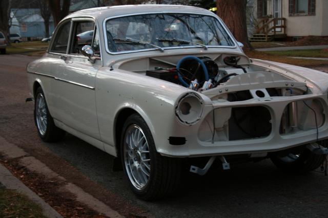
I figured it was time to bring this thread back from the dead. With the recent problems with running have continued I've pulled out all the stops to get the car working right. So here's what has happened recently. First, Ian kindly drove down to Lethbridge to "fine tooth" the car. He went over every inch and found a few things that were in need of tweeks. We both pondered the various problems and made a few major changes (I'll show those in a bit).

Next, Rhys Kent of SU carb fame was contacted. Rhys is a great guy and sold me the SU parts for the HIF rebuilds. He stands behind his product and spent 2 hours on the phone with me working through the issues. He'll have the carbs and my spares to go over on Tuesday and will get them back to me by Thursday. We suspect throttle shaft wear and the decel valves.

So that should be good.

Back to what Ian and I figured out. There were a number of lines and things that needed tidying up (all details) and tying down. The spedo cable went in, the plumbing was pondered (*There was a check valve in the block heater #-o ). Ian figured that putting the temp sender in the head was a better idea than putting it in the block and given that I don't have the block heater any longer, this was a pretty good idea.

So the temp sender is now right beside the thermostat. I fabricated up a block for it to sit in.

Image

Image

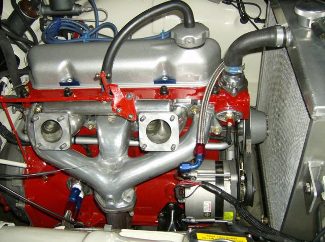
This should give the e-fan the correct temp signal and should also stop bleeding off the hot coolant in advance of the radiator. A plug was installed at the back of the block and the cooling system refilled from the block (the rad was piched off while the hoses were removed).

Image

The new fuel line is all braded and goes in the stock location - all fuel pressure regulators were removed.

Image

A hard line was created to go from the rad to the puke tank.

Image

That's pretty much all I've got to report until the carbs return and we fire it up and see what effect all the changes have on the engine. Thanks again to Ian and Greg for helping out this weekend.

_________________
Coburn Performance - OCD comes naturally.


Top
 Profile  
 
 Post subject: Re: The B20 Assembly Thread
PostPosted: Mon May 04, 2009 11:13 am 
Haha, I just built a W24 Octo-Turbo, now what?!
User avatar

Joined: Wed Dec 21, 2005 8:40 pm
Posts: 3492
Location: Calgary, Ab
I just noticed that you've got the crankcase ventilation connected directly to full manifold vacuum... I really don't like that. You tend to draw in lots of air past the seals, drawing dust & dirt along with it, shortening the life of the oil. If you've got any leaks in that system you can also cause lean running during high vacuum situations (hmm...)

If you can stand the smell, route the crankcase vent to a catch can and stick a filter on the outlet to avoid drawing anything back in, and plug off the manifold. If not, you could add a check valve (look at the ones in the Pulsair system in your 242) to the collector of the downpipe to put a small vaccum draw on the crankcase and mix the crankcase vent with the exhaust to reduce/mask the stink.

Lots of times a carburated car will connect one valve cover to the intake manifold, but there will be a filter or a vent or some other form of vacuum relief. Other times the crankcase vent will go to a ported vacuum source, that only delivers partial vacuum at certain throttle openings. Other times the crankcase vent will have a small hose connected to the manifold to provide some vacuum, and a bigger hose will continue on to the air cleaner. Either way that "unmetered" air must be accounted for in the jetting. The way you've got it, you MAY have unmetered air (coming past the seals) and you may not. I'm not familiar with your oil filler cap - it might have a vacuum relief built into it, and that nipple on the manifold might have a teeny-weeny aperture in it to reduce the flow of unmetered air to a trickle.

Something to look at, anyway.

Edit - whoops, just noticed the breather box on the side of the engine. Where's that hose on top of the box go?


Top
 Profile  
 
 Post subject: Re: The B20 Assembly Thread
PostPosted: Mon May 04, 2009 11:41 am 
Haha, I just built a W24 Octo-Turbo, now what?!
User avatar

Joined: Wed Jun 14, 2006 4:19 pm
Posts: 3131
Location: Lethbridge, AB
The PCV system on the B20 works like this...there is a tiny hole in the nipple on the intake that leads to the oil filler cap, the box on the side of the engine is connected to the rear carb. So air flow goes from the carb (filtered) to the block then up through the block into the intake for ignition. I could run it to another puke tank, but it isn't going to happen for a while. I'm guessing most of the objection is based on a loss of perforance from burning the crap coming out of the crankcase?

_________________
Coburn Performance - OCD comes naturally.


Top
 Profile  
 
 Post subject: Re: The B20 Assembly Thread
PostPosted: Mon May 04, 2009 11:54 am 
Cams + Headers

Joined: Sat Feb 28, 2009 6:55 pm
Posts: 55
I, like others stand in awe of your work. With the help of Rhys I am sorting out my HIF's. I originally had my crankcase hoses hooked up as you do. This, apparently is how B18's work. However, on the B20 with HIFs the oil cap hose goes to the air filter and the oil trap hose goes to the manifold inlet. The manifold nipple for the HIFs has a 1/16" hole in it. I'm certainly no expert, just passing on what I have learned hope this helps. Bill


Top
 Profile  
 
 Post subject: Re: The B20 Assembly Thread
PostPosted: Mon May 04, 2009 12:29 pm 
Haha, I just built a W24 Octo-Turbo, now what?!
User avatar

Joined: Wed Dec 21, 2005 8:40 pm
Posts: 3492
Location: Calgary, Ab
No, the burnage of crap is something I always try to do myself, but you have to be careful how you do it.

My main objections would be: a) the excessive vacuum in the case, which is relieved by the filtered air inlet going to your oil box; and b) the amount of unmetered air that screws up the signal to your carbs, which is alleviated by the tiny orifice in the manifold.

However, Mr. Bones brings up another good point: on my Mini, the only way for the crankcase pressure to leave the engine was through the valve cover vent, and at some point the pressure in the block would overcome the gravity that's trying to pull the oil through the returns, and the engine would start pumping oil out the breather. Your engine flows fresh air and crankcase gasses upwards, and if you get enough flow (unlikely - you should have seen the blowby my Mini made) you'll start feeding oil into your intake manifold. The oil separator box will do a much better job of letting the oil settle out, plus it's not subjected to direct spray (like what's coming off your rockers) so there will be less liquid oil headed towards the intake.

So I guess I have a third and fourth objection: c) the amount of liquid oil being drawn along with the crankcase ventilation gas; and d) the possibility for poor head drainage by the airflow through the engine fighting it, rather than helping it.

Edit - the poor drainage problem is reduced by the restriction in the intake manifold reducing airflow, and the oil cap might be really efficient at separating oil and gas for all I know.

You must think I live to poke holes in your work, Craig. Not true - I'm just looking for alternatives to why your engine isn't running properly.

Regarding your post below: I have never seen the reason why any car should have a PCV valve. Those things are more trouble than they're worth, and I can't think of any reason why you'd add what amounts to a check valve in an airstream where 99.99999% of the time air is flowing in the direction you want it to. Volvo eliminated such nonsenses as flame traps and PCV valves for the turbo models, primarily because the PCV system isn't connected to the intake manifold (which I also believe to be the "right" way).


Top
 Profile  
 
 Post subject: Re: The B20 Assembly Thread
PostPosted: Mon May 04, 2009 12:38 pm 
Haha, I just built a W24 Octo-Turbo, now what?!
User avatar

Joined: Wed Jun 14, 2006 4:19 pm
Posts: 3131
Location: Lethbridge, AB
Hi Bill,

The PCV set up on a B20 is plumbed exactly the reverse of the B18. In a B18, there is a air filter plate on the carbs that feeds air into the oil filler cap, the flame trap on the engine is fed (via a PCV check valve) to the nipple on the intake - that nipple is a straight port arrangement as the air draw is limited by the filter plate.

On the B20, the air flow is reversed. The air comes in thought the carb filter element and goes into the flame trap, it then gets drawn through the engine via engine vacuum signal to and drawn out the oil filler cap (which is equiped with a stainless "scouring pad" to strip out the oil).

See http://www.k-jet.org/files/greenbooks/v ... A_B20B.pdf (page 2-15)

This conversion was made as this system was more reliable than the B18's as there was no PCV valve to foul. When the B18's wear, the valve would stick, pressurize the crank case and send crap everywhere - oil leaks, dipsticks blown out of tubes, foamy oil crap sticking up your SU's - ask how I know.

_________________
Coburn Performance - OCD comes naturally.


Top
 Profile  
 
 Post subject: Re: The B20 Assembly Thread
PostPosted: Mon May 04, 2009 12:48 pm 
Haha, I just built a W24 Octo-Turbo, now what?!
User avatar

Joined: Wed Jun 14, 2006 4:19 pm
Posts: 3131
Location: Lethbridge, AB
Ugly Duck wrote:
No, the burnage of crap is something I always try to do myself, but you have to be careful how you do it.

My main objections would be: a) the excessive vacuum in the case, which is relieved by the filtered air inlet going to your oil box; and b) the amount of unmetered air that screws up the signal to your carbs, which is alleviated by the tiny orifice in the manifold.

However, Mr. Bones brings up another good point: on my Mini, the only way for the crankcase pressure to leave the engine was through the valve cover vent, and at some point the pressure in the block would overcome the gravity that's trying to pull the oil through the returns, and the engine would start pumping oil out the breather. Your engine flows fresh air and crankcase gasses upwards, and if you get enough flow (unlikely - you should have seen the blowby my Mini made) you'll start feeding oil into your intake manifold. The oil separator box will do a much better job of letting the oil settle out, plus it's not subjected to direct spray (like what's coming off your rockers) so there will be less liquid oil headed towards the intake.

So I guess I have a third and fourth objection: c) the amount of liquid oil being drawn along with the crankcase ventilation gas; and d) the possibility for poor head drainage by the airflow through the engine fighting it, rather than helping it.


This is pretty much the exact thing we were seeing on the Smurf yesterday. He's got plenty of blow by and is puking foamy oil and crap into his intake track. The ultimate in anti performance. So, at this point I now that this is not an ultimate system and I should plumb a puke tin into it to strip out the oil, but I'm completly brain dead with work and other pressures and there isn't a hope in hell of me devoting any time to making that set up look pretty right now.

Like I said, I'll drive it like this for a while and worry about where to route the gasses and puke tins later. In fact it is half there, the JIC fitting out of the flame trap could be routed just past the rear carb (longer hose) and a puke tin could be placed where I once had my block heater. Then route the gasses back into the intake via the port. The line from the manifold to the oil filler could be blocked and a wee filter placed on the oil filler cap. That would work...I think.

_________________
Coburn Performance - OCD comes naturally.


Top
 Profile  
 
 Post subject: Re: The B20 Assembly Thread
PostPosted: Mon May 04, 2009 1:06 pm 
Haha, I just built a W24 Octo-Turbo, now what?!
User avatar

Joined: Wed Dec 21, 2005 8:40 pm
Posts: 3492
Location: Calgary, Ab
Hmm... let me think about that for a minute.

You'd use the port on the air filter to coax gas through the puke tank and a bunch of hose, and then fresh air would be drawn through a breather filter and into the valve cover? I'm not sure, but I think the gas will take the path of least resistance, and to me the least resistance will be up and out the breather rather than through all that hose, considering the minute pressure drop across the air filter.

Then there's the possibility that one carb is breathing "sour" gas and one is getting fresh air/fuel mix.

No, I think I'd go Air Filter -> oil filler cap -> through engine -> separator box -> puke tank -> intake manifold. Get rid of the flame trap, because if you backfire and the gas in the puke tank catches, the flame trap will probably get shot into your engine. Honestly, I think the puke tank is an unnecessary extra until you've got lots of blowby. Flame traps and PCV valves do plug up and will cause trouble eventually, especially on an older engine, so design the system without them. Anyway, I would be hard pressed to believe that flame would shoot out the little orifice in the manifold nipple during a backfire.

But you're right - unless you've changed something in the Volvo-supplied system, it's probably going to work just fine for a fresh engine. Pull the hose from the oil cap once in a while to see how much oil has passed through it and decide if you want to change anything.


Top
 Profile  
 
 Post subject: Re: The B20 Assembly Thread
PostPosted: Mon May 04, 2009 1:23 pm 
Haha, I just built a W24 Octo-Turbo, now what?!
User avatar

Joined: Wed Jun 14, 2006 4:19 pm
Posts: 3131
Location: Lethbridge, AB
Ugly Duck wrote:
Hmm... let me think about that for a minute.

You'd use the port on the air filter to coax gas through the puke tank and a bunch of hose, and then fresh air would be drawn through a breather filter and into the valve cover? I'm not sure, but I think the gas will take the path of least resistance, and to me the least resistance will be up and out the breather rather than through all that hose, considering the minute pressure drop across the air filter.

Then there's the possibility that one carb is breathing "sour" gas and one is getting fresh air/fuel mix.

No, I think I'd go Air Filter -> oil filler cap -> through engine -> separator box -> puke tank -> intake manifold. Get rid of the flame trap, because if you backfire and the gas in the puke tank catches, the flame trap will probably get shot into your engine. Honestly, I think the puke tank is an unnecessary extra until you've got lots of blowby. Flame traps and PCV valves do plug up and will cause trouble eventually, especially on an older engine, so design the system without them. Anyway, I would be hard pressed to believe that flame would shoot out the little orifice in the manifold nipple during a backfire.

But you're right - unless you've changed something in the Volvo-supplied system, it's probably going to work just fine for a fresh engine. Pull the hose from the oil cap once in a while to see how much oil has passed through it and decide if you want to change anything.


I didn't explain my routing very well. It is the same in my head as what you've proposed except that I didn't put the hose from the air filter to the oil filler cap, but just put a filter on it. No matter, as you've pointed out, I've got the correct routing for the stock system and don't expect any blow-by for the first few miles.

_________________
Coburn Performance - OCD comes naturally.


Top
 Profile  
 
 Post subject: Re: The B20 Assembly Thread
PostPosted: Mon May 04, 2009 9:43 pm 
Cams + Headers

Joined: Sat Feb 28, 2009 6:55 pm
Posts: 55
Craig: My bad. I was repeating info I received from Rhys. I checked the manual. You are correct. Means I have to redo some plumbing!

Bill


Top
 Profile  
 
 Post subject: Re: The B20 Assembly Thread
PostPosted: Tue May 05, 2009 5:09 am 
Strapping on extra booster rockets
User avatar

Joined: Tue Apr 22, 2008 5:43 am
Posts: 387
I read part of this post..fire your machinist ..
your cross hatch is backwards in your cylinders. do a blow up of the pic.
and put a fuel return line in.(it doesnt hurt and only helps)

_________________
Bert & Jacks Auto Service
129 17th ave S.E
228-7078
Paul


Top
 Profile  
 
 Post subject: Re: The B20 Assembly Thread
PostPosted: Tue May 05, 2009 7:22 am 
Haha, I just built a W24 Octo-Turbo, now what?!

Joined: Wed Dec 21, 2005 8:03 pm
Posts: 2859
Location: T2C
CANCER MAN wrote:
and put a fuel return line in.(it doesnt hurt and only helps)


I'm curious Paul. Just where does this return line come from? The SU is a bit of a dead end street in terms of fuel flow. Without some sort of choke in the line I suspect all it would do is syphon all the fuel in the line back to the tank making starting that much more difficult. Keeping a little pressure between the pump and the carbs will help prevent vaporization in the line. Please explain...

_________________
Dale

'67 123GT
'67 122s
'99 AMG E55T


Top
 Profile  
 
Display posts from previous:  Sort by  
Post a new topicPost a reply Page 9 of 54   [ 801 posts ]
Go to page Previous  1 ... 6, 7, 8, 9, 10, 11, 12 ... 54  Next


Who is online

Users browsing this forum: No registered users and 1 guest


You cannot post new topics in this forum
You cannot reply to topics in this forum
You cannot edit your posts in this forum
You cannot delete your posts in this forum
You cannot post attachments in this forum

Jump to:  
cron


Powered by phpBB © 2000, 2002, 2005, 2007 phpBB Group
610nm Style by Daniel St. Jules of Gamexe.net