Hi Guys,
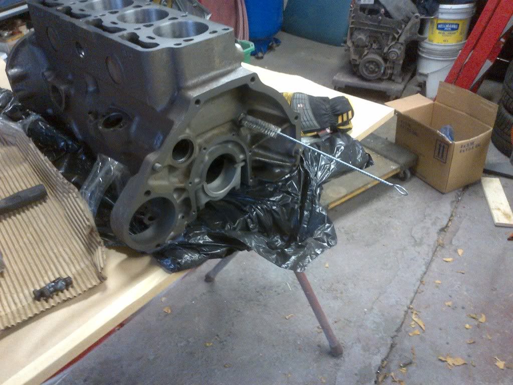
I finally found a buyer for the B18 that use to power the Canuck. I did the head a year of so ago but have been tripping over the short block on my garage floor for almost three years. John Paulsen needed an engine for his 1962 122 rebuild and this engine fit the bill. So I finally stripped it down to get the rebuild started. On the way by I decided to take a few shots of what I do when I strip an engine.
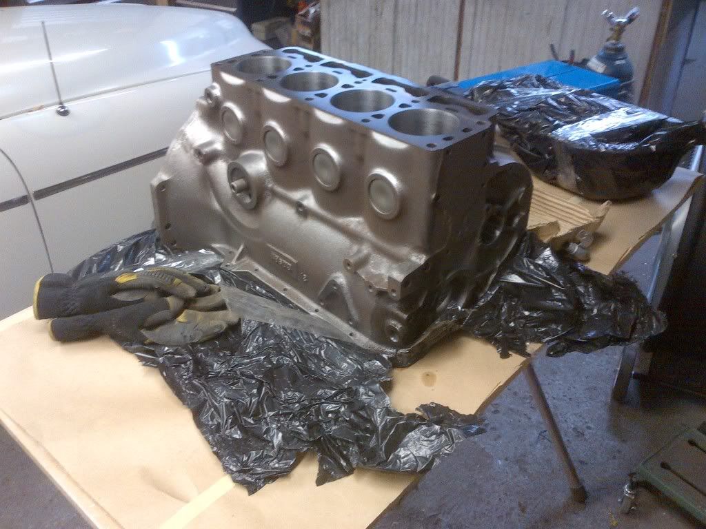
Here's the how-to. First up, I knew that the engine was in good shape generally as there was hardly any ridge at the top of the cylinders. Tearing an engine down is a great way to see what has happened to the engine over the years. The previous owner had spent a thousand dollars on a used bottom end, then it started to make noises due to a separated cam gear. With this in mind, let's have a look at what I found.
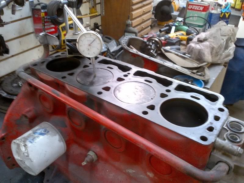
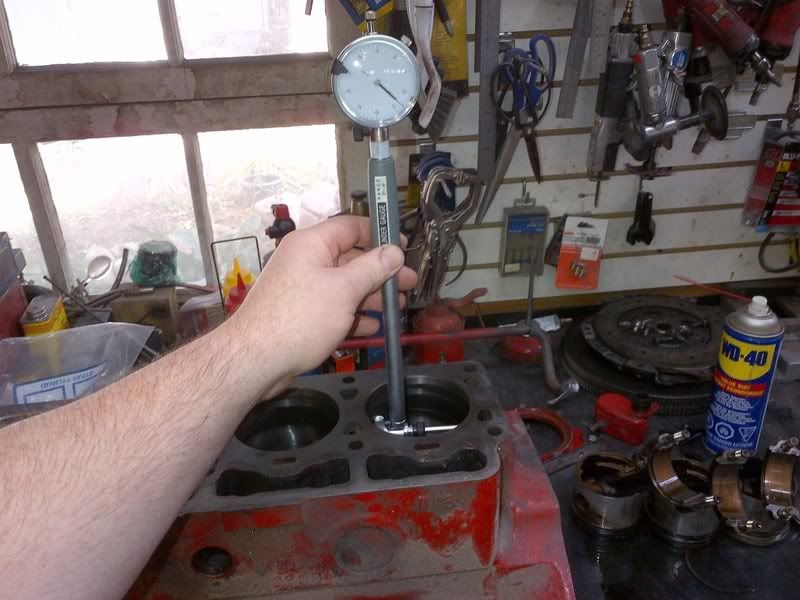
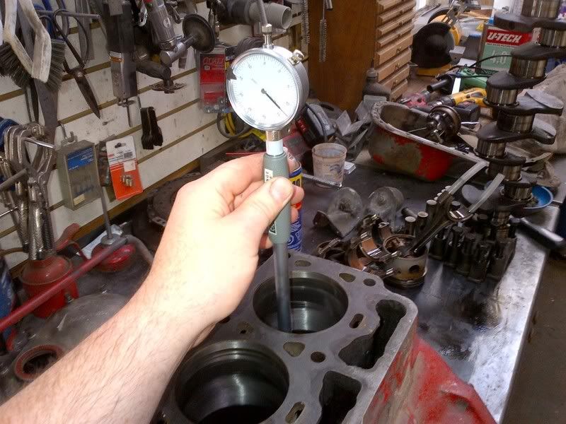
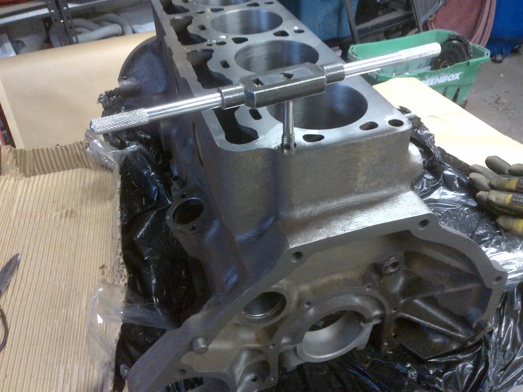
First, the pistons are rotated to TDC and the carbon is carefully removed. Then it's time to check the deck height. Given the thickness of the head gasket, I like to "zero deck" the block. Check for TDC using a dial indicator.
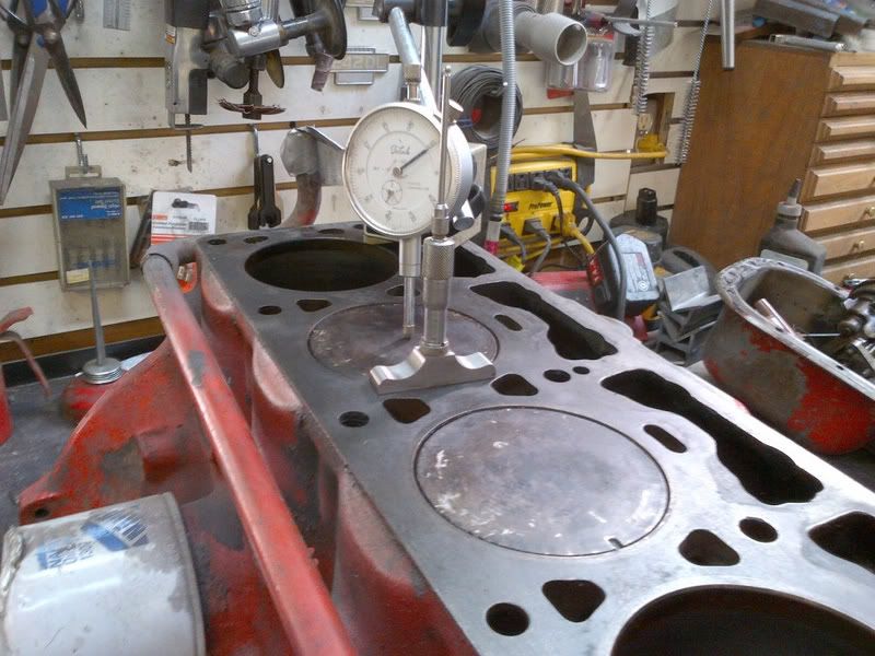
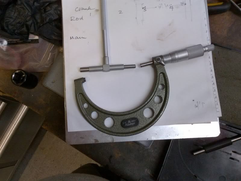
Then measure how much the pistons are recessed in the bore for all pistons - they should be the same. For this engine 20 thou will get the pistons flush to the top of the block. Measurements are made with a depth micrometer in line with the crank.
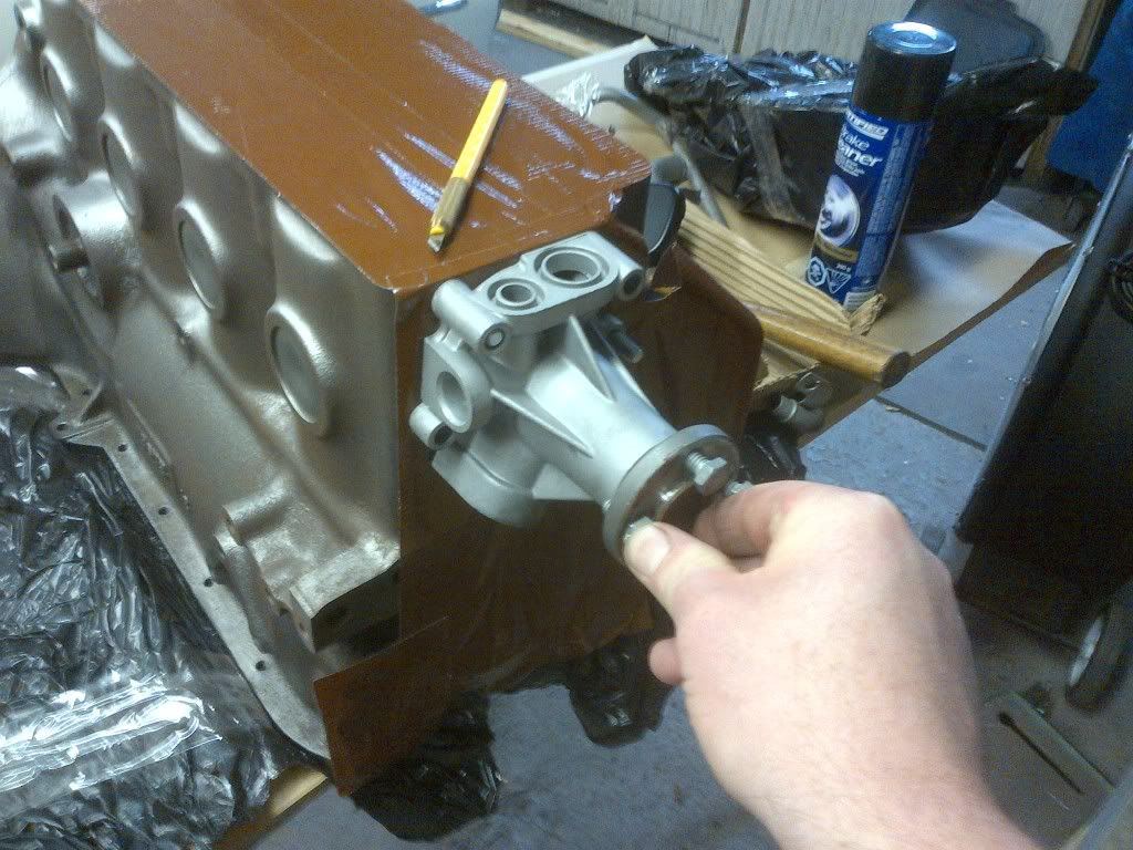
Lifters are then removed along with the water pump, front timing cover, distributor, and the rear main seal. Not all of the lifters would come out the top. Not a good sign. These engines are famously hard on valve train components. Have a look at the face of these lifters. That's a lot of wear. Never reuse lifters - these ones are junk and have been tossed.
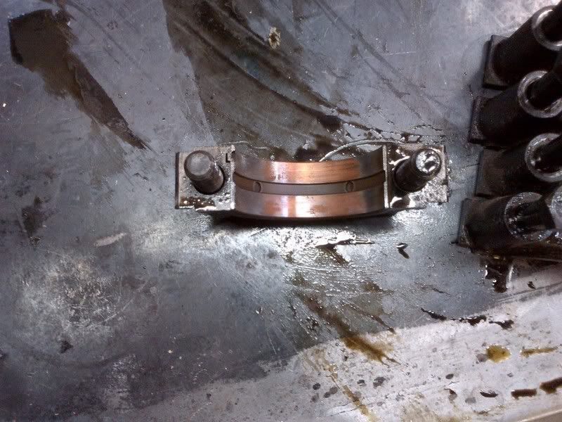
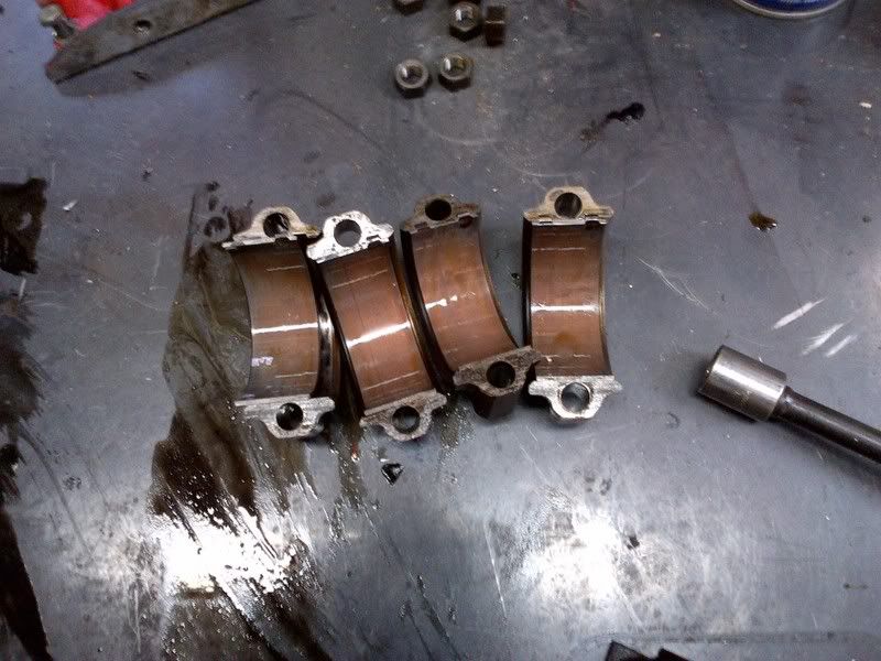
The main bearing caps are then removed and checked for wear. Here we see that the babbitt has been lost and we are down the the copper. This is normal for a high-mileage engine and it is good to see that we didn't hit the bearing shell.
Rod end caps are removed and the bearings are inspected - same evidence of wear - note the consistency of the wear. These bearings are toast, but no nasty score marks and just down to the copper. When you get past this layer of metal, cranks usually need to be reground.
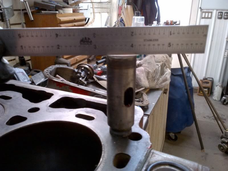
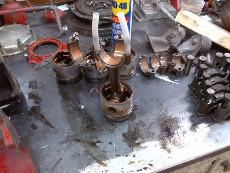
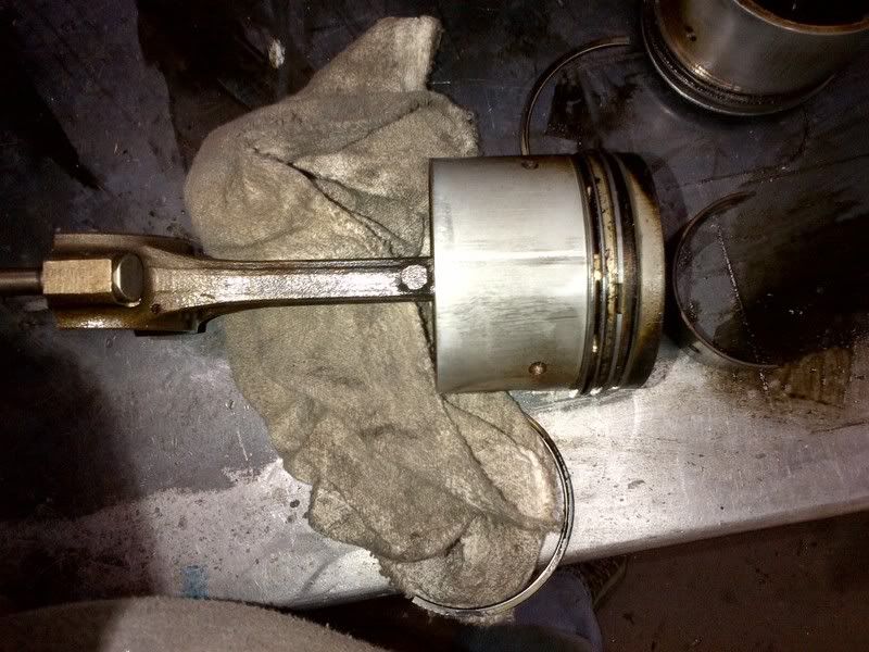
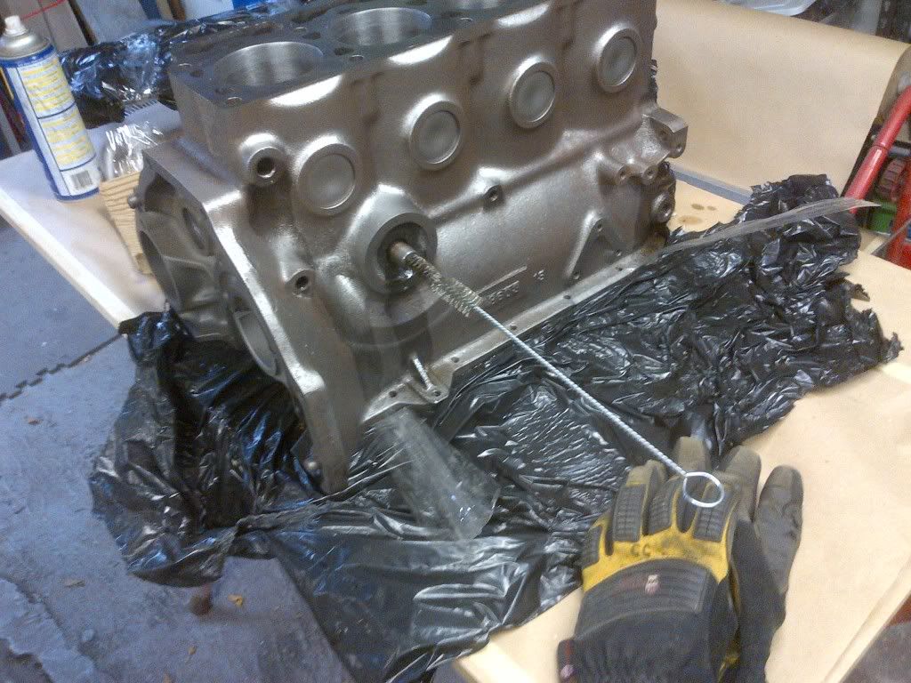
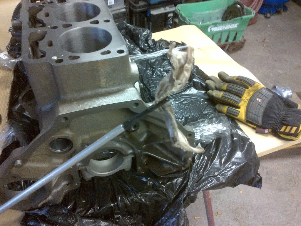
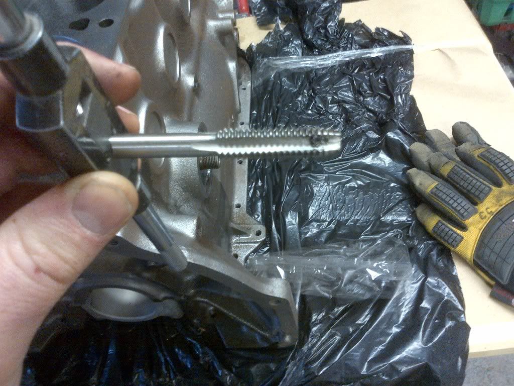
The crank is then removed and wiped down for measurement. Next up the pistons have to come out of the bores. The ridge at the top of the cylinder has to be smoothed out so that the rings don't break out and damage either the piston or the bore when you remove the piston. I fit protectors to the rod bolts so they don't score the bores.
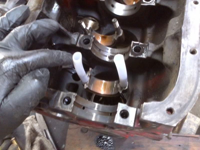
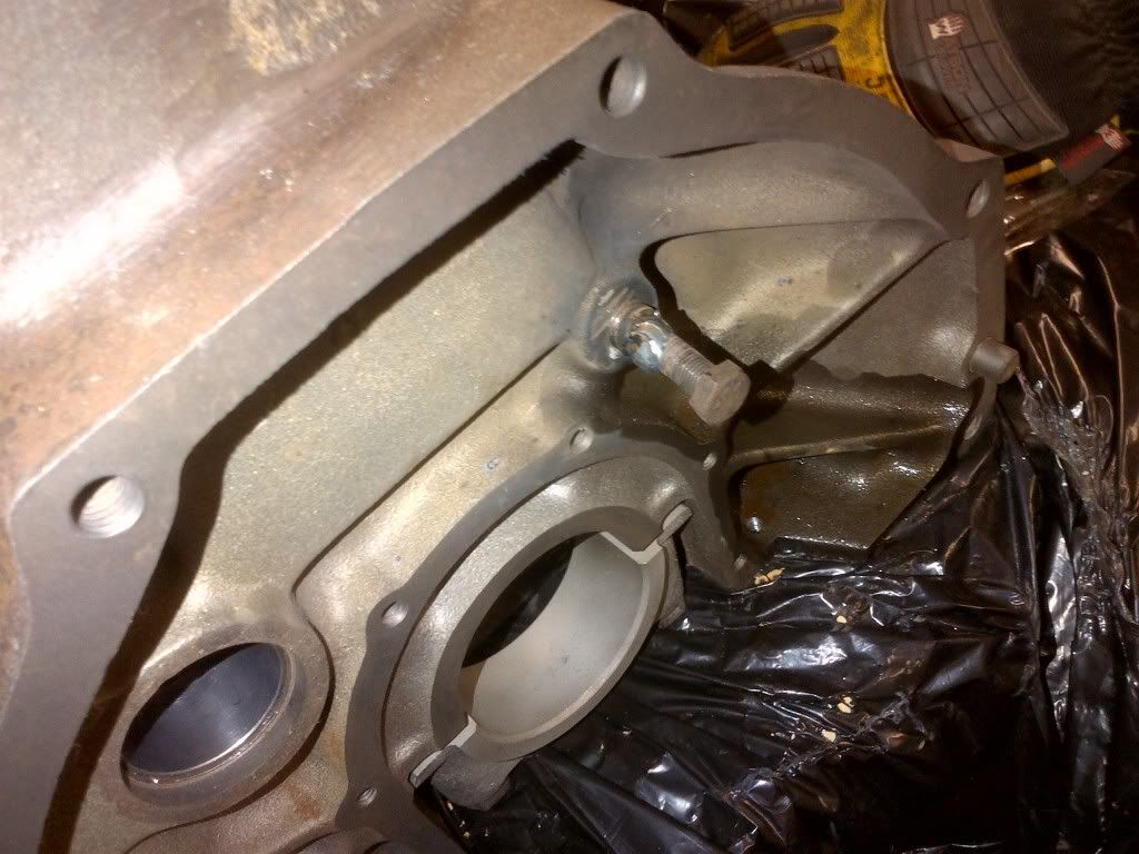
Note the rear main seal in the background - it is the more modern silicon seal, but was not correctly fitted and was leaking. Someone had replaced it recently (ish).
The pistons show just a light scuff on the base of the piston - remarkable given the condition of the rest of the engine. First picture shows the thrust side.
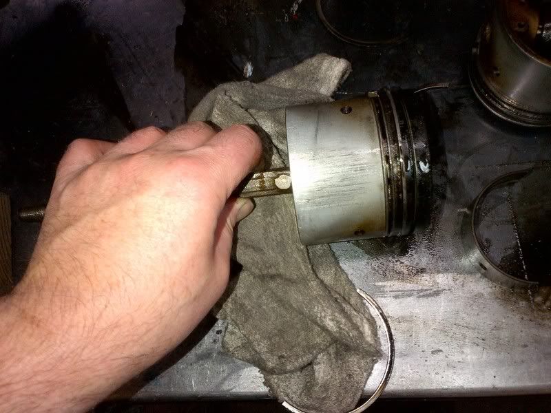
This is the other side - hardly a mark. They measured on spec - new rings and they are good to go after a cleaning.
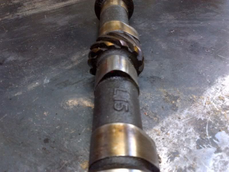
Then the cam is extracted - here is a reasonable cam lobe.
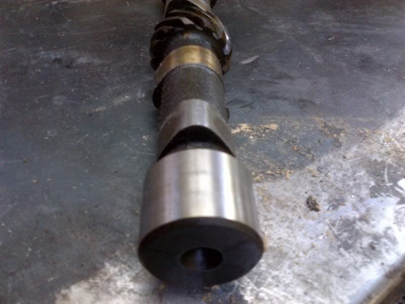
Here is one that is not so reasonable. This cam is not doing much without a lobe

All bearing surfaces on the crank are then inspected for roundness by measuring them perpendicular to the counter-weights and parallel to the counter weights.
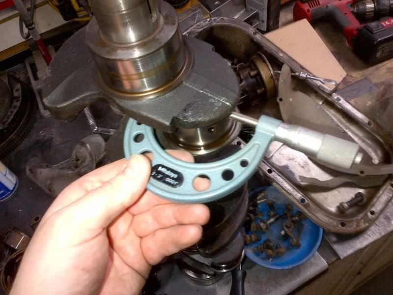
This crank was dead on what it should be (mains and rod), so a light polish is all that is needed at the machine shop to get it back to spec.
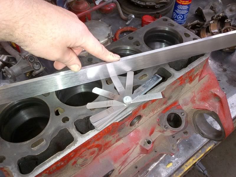
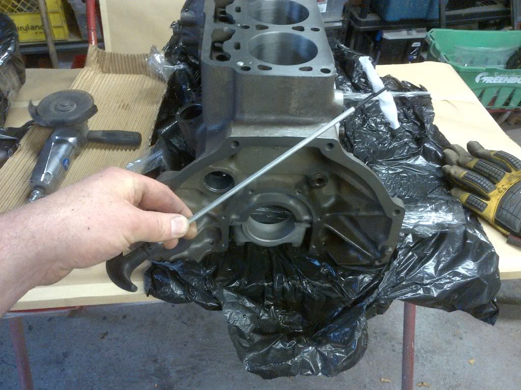
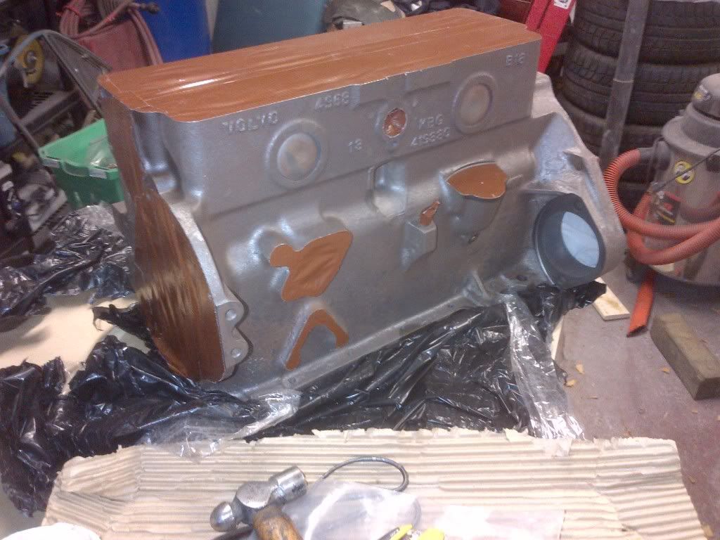
The block is checked for straight - I could just get a 2 thou feeler gauge under my straight edge under in the middle. This is on spec, but as the block is being decked I just wanted to check. I've never found a Volvo block that is out of spec.
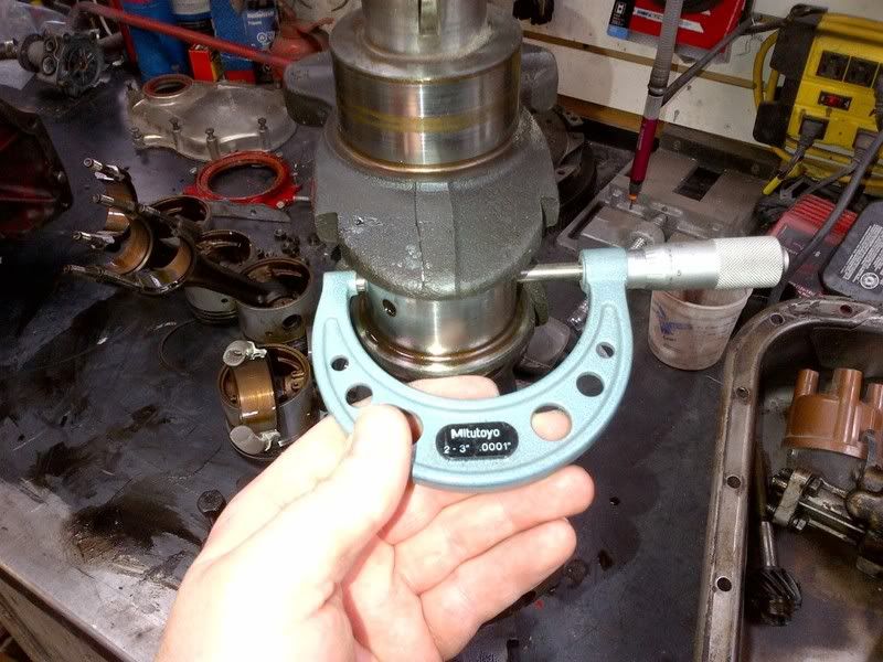
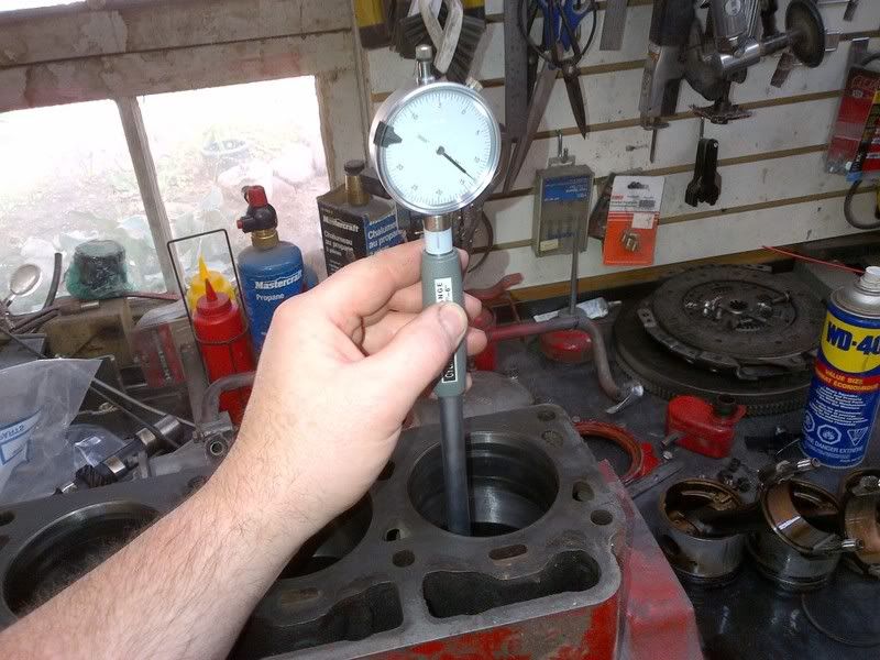
The bores are then measured at the top and the bottom in line and perpendicular to the long axis of the crank. You can see the hone marks where I removed the ridge to extract the piston. These bores are less than 5 thou out of round. New oversize rings will be all that is required to get it all sealed up again.
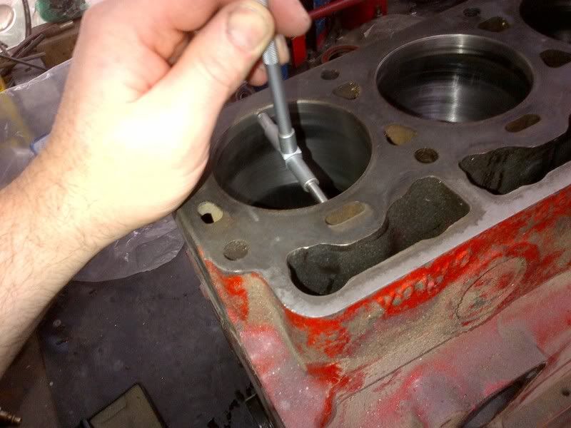
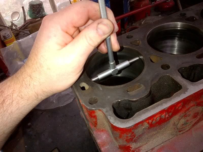
I use telescoping gauges (though I do have inside micrometers) - cheap telescoping gauges are junk and should be tossed. I've got a nice set of Japanese made telescoping gauges with stiff springs. There is still a bit of an art to doing these measurements. I wiggle them around, lock them down and measure a couple of times. They are easier to use than inside mic's when you have to measure deep in a bore. Once locked, the gauge us rolled out of the bore - measure the perpendicular axis first as it will be larger.
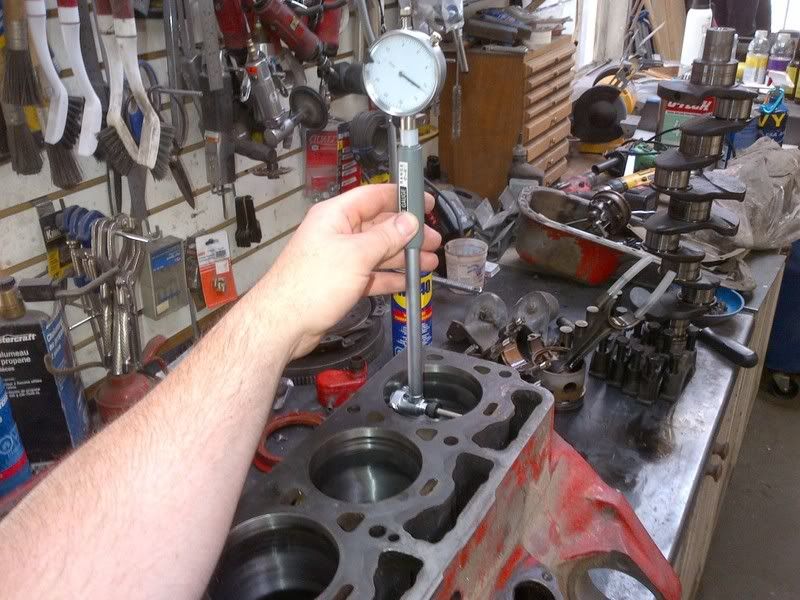
I then double check the bores for round with a bore gauge - starting at top and travelling down to the bottom. The inline measurement was dead (0) and the perpendicular measurement had 5 thou of taper for all cylinders.
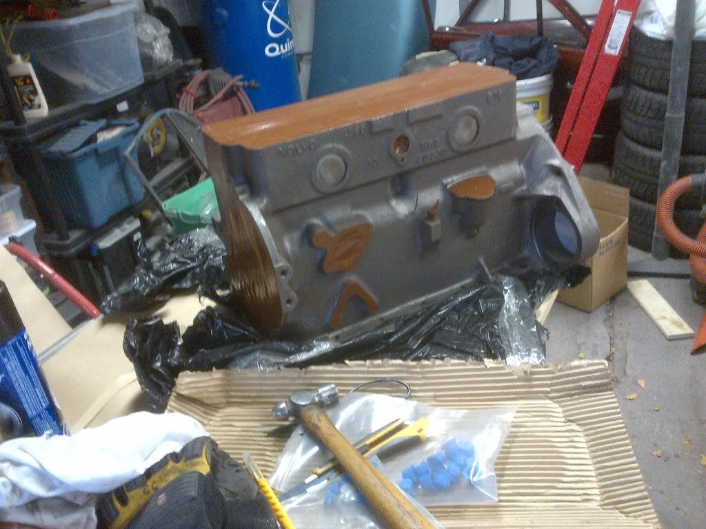
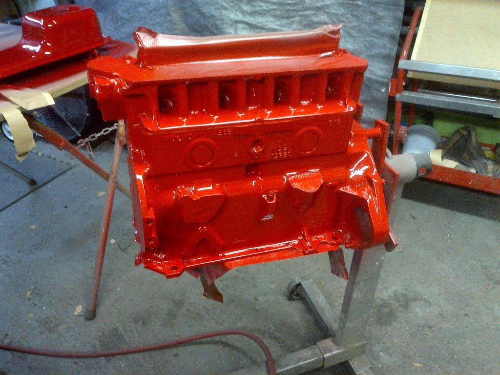
That's it - the block and parts are then sent off to the machine shop for their work to be done. I did check the main line of the block and it was dead straight. So this engine needs new standard size bearings all round, a light hone and a little off the top and it will be back in service. I get the machine shop to bake all parts and clean them (except the block - I do that, no sense paying someone for something that you're going to do again anyway. Baking removes all the carbon and paint and the guys bead blast the rust off other parts (water transfer tubes etc). I'll keep this going as I get the parts back.


 I guess that would mean I'm not coming to get it Friday then?