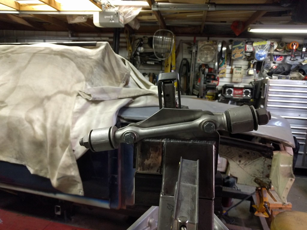
Quick update. I'm waiting on the laser guy to cut all the brackets and stuff that I designed for the new front end. I got the confirmation from Art Morrison Enterprises that the can do something for the build. It won't be one piece the way I wanted as the die (shown in the post above) needs about 9" of material to trace through a bend for grip. We have 6". So I'm getting two piece parts that I will then weld together.
Here's the drawing if people are interested.
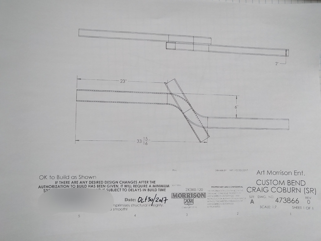
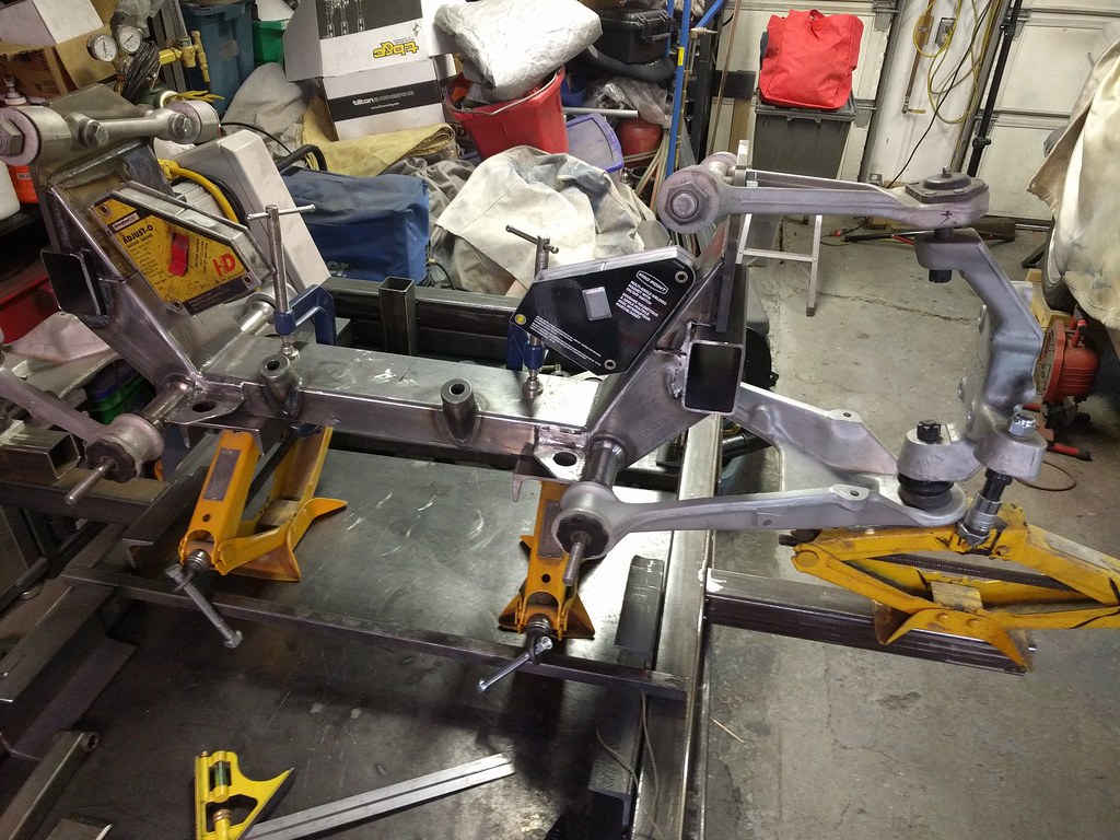
I don't have a complete drawing of the entire front end design. It's a remix of various ideas and constraints I've seen for other projects dealing with Corvette suspensions. It all starts with the LCA - We're going to rely on a longitudinal tube to establish the reference plane to attach the laser cut brackets to provide the accuracy needed. The ends of this tube have round tube parts to provide an attachment point to the frame rail. The front will be 1.5" 120 wall square tube and the rear will be 1.5 X 2.5" 120 wall tube mounted in the 1.5" direction so that the additional rear position forces can be managed.
So I carefully transferred all the dimensions off this crappy cross member one more time. Broke out the CAD and got it all modelled up and off to the laser cutter.
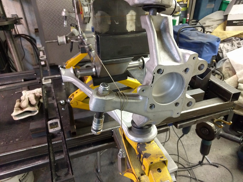
For optimal Ackermann this is the steering centre line.
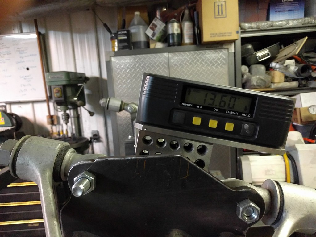
Angles and more angles.
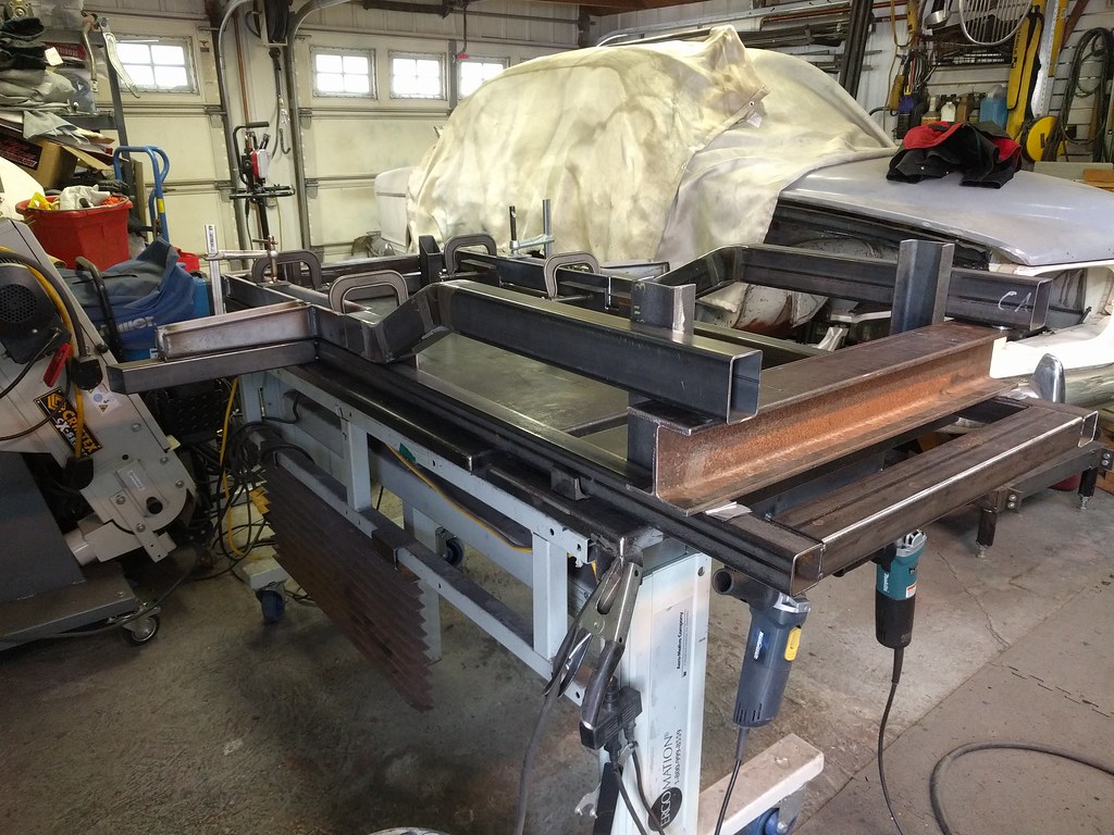
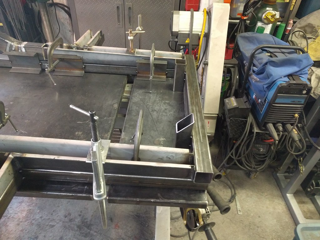
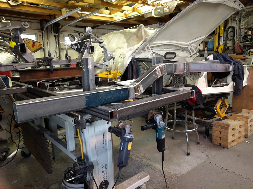
These are the start parts. I was super pissed off about this entire build being stalled...so these parts have 5 thou of variance (total - using variance in the statistical sense - square it if you want the standard deviation - they're f'ing perfect - take that you hot rod piece of garbage).
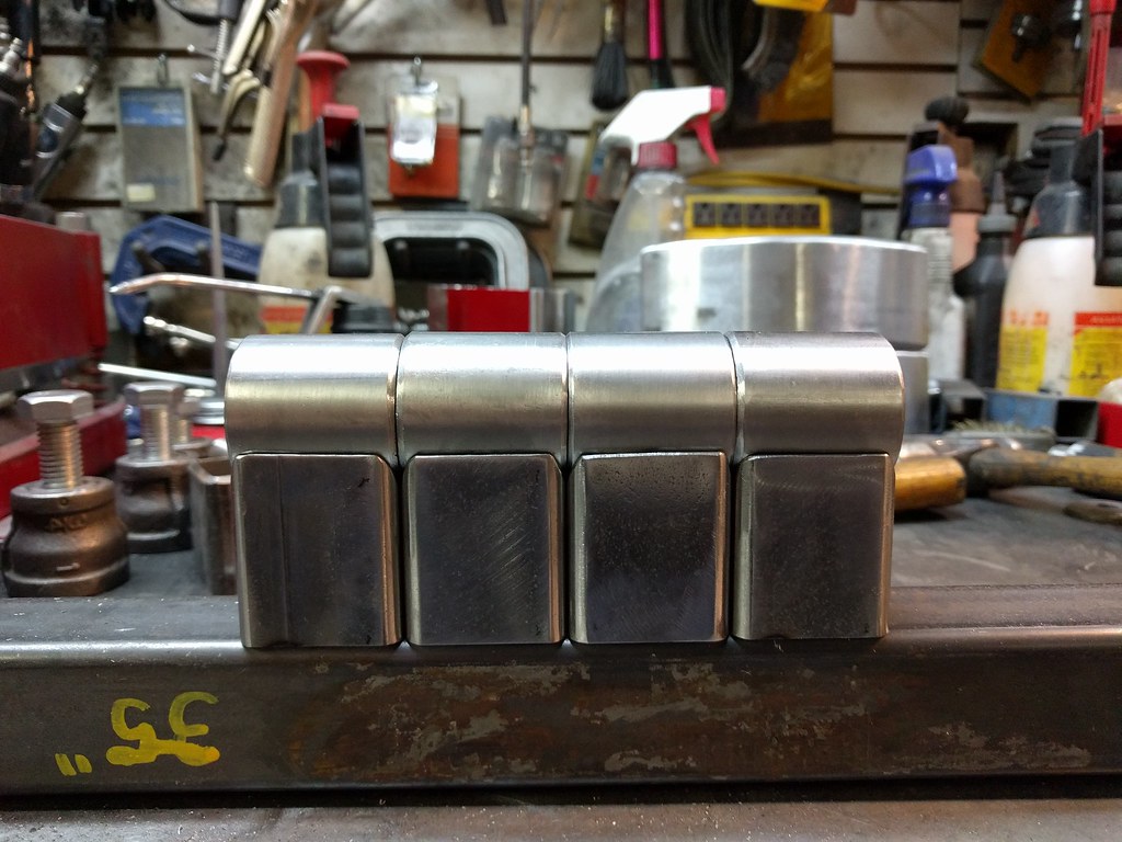
All of the mill scale is cleaned off the weld areas prior to TIG'ing it all up.
You can sort of see the idea here. I should learn to photograph the welds better. They are nicer in reality than they look here.
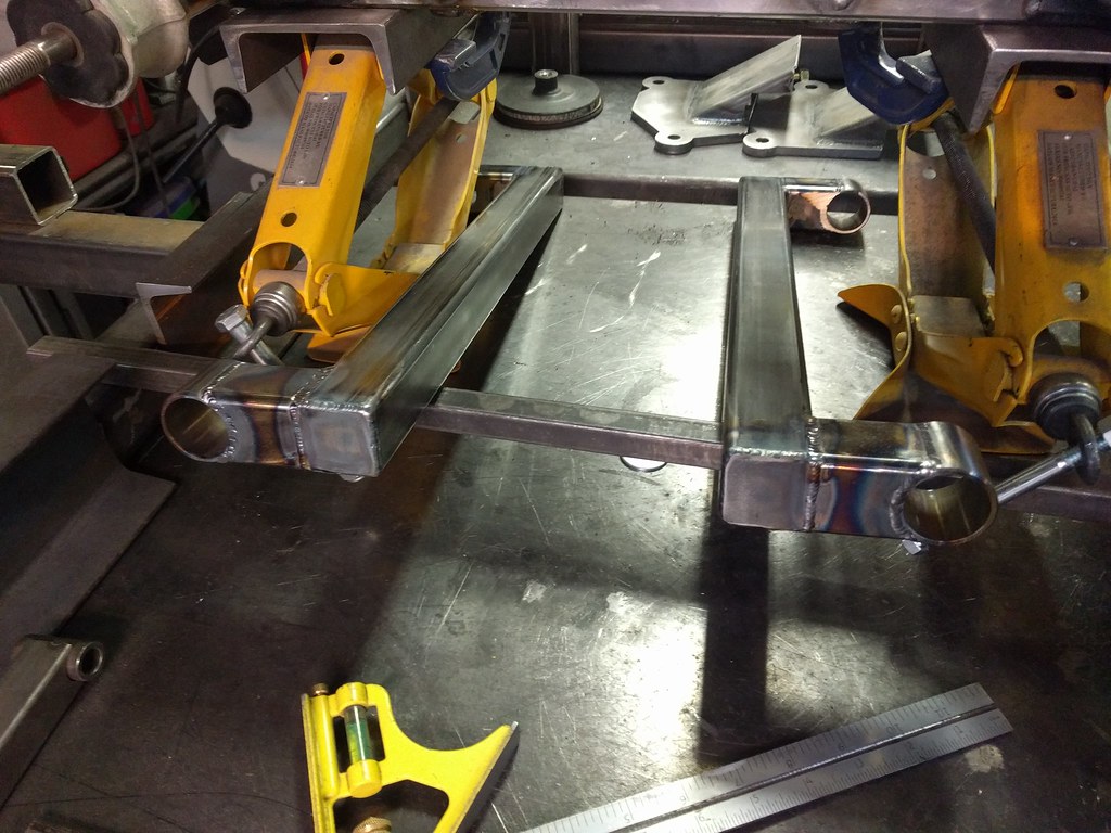
A quick check with the oil pan shows the first consequence of doing the cross member this way - that fat-arsed pan is going to have to shrink a little. No biggie.
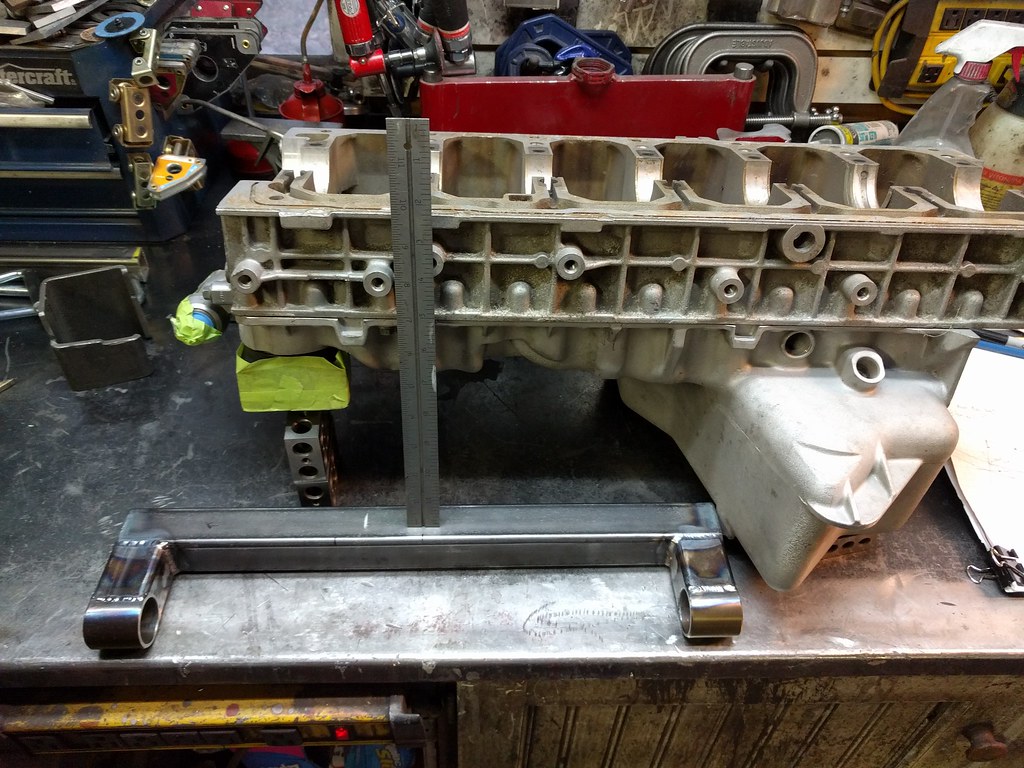
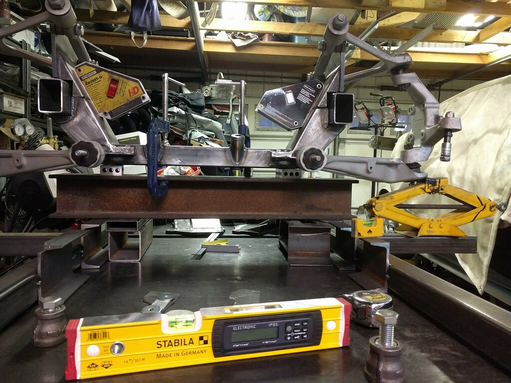
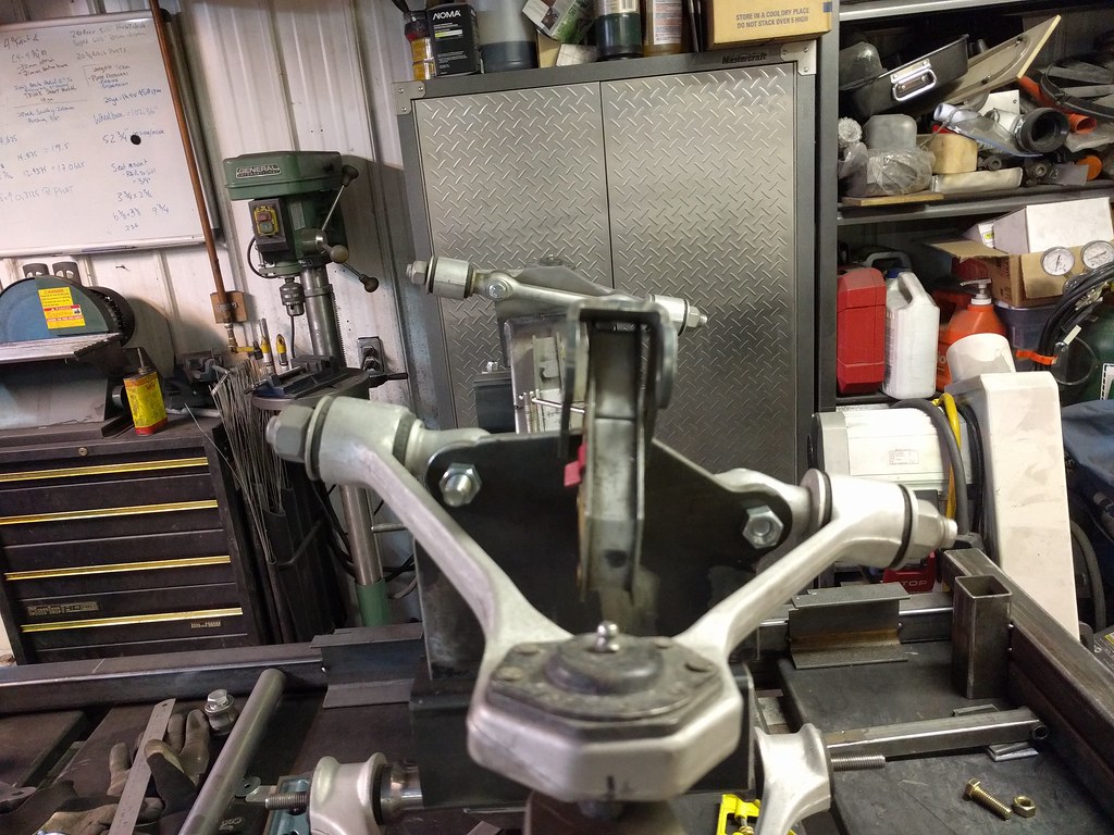
The soapstone line shows where the steering axis will be. We're going to be needing a bracket.
The real CAD.

This will be cut from 3/8" plate and have through brackets and be capped and all the strength that is needed. It'll be fun to weld up, I may even need to break out the 7018!
With that sitting on the bench, it's time to toss the engine and trans into the engine bay for the first time.
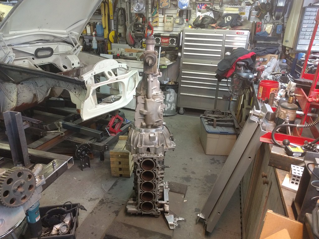
We all know it fits...but whatever.
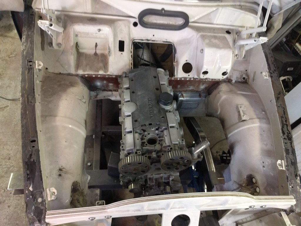
Still needs a little more up at the back.

I'll have to cut a bit more out of the tunnel.
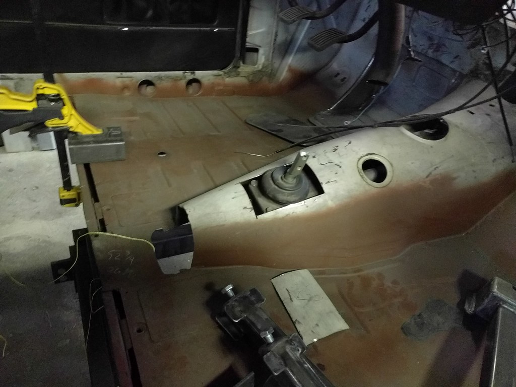
Floor mount pedal box clears nicely.

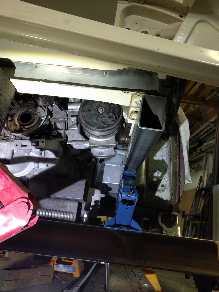
Bottom starter bolt is going to be an issue - the engine still has to come forward about a half inch.
I think once the tilt is settled, this clearance for the cam position sensor etc will be fine.

Even with the new frame rail being 1.5" taller, the AC compressor bolts are still going to be an issue - but I don't mind creating a little notch to get them out and installed. So that looks good.
And that's where we sit as of now.