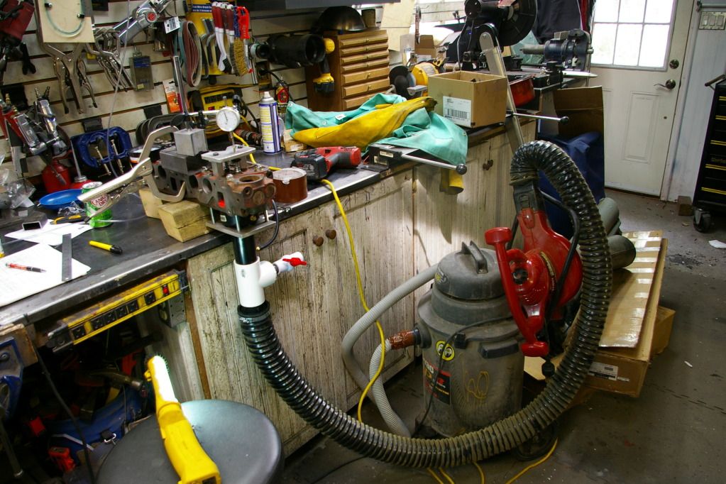
Flow bench time. First up - I can't generate 28" Hg with my shop vac...so we have to take things with a little caution. I tested both with vacuum and with air pressure at 100 psi. Here's what my rig looks like.
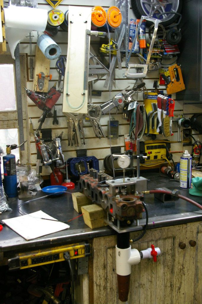
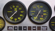
You can see the important parts, the heart of the beast is my shop vac, this runs through a hose to the base 2" ABS pipe, then up to a tee where I've installed a ball valve as a bleed. Next it flows into a 2 - 3 ABS fitting that is the same size as the cylinder bore. I've tapped a hole after the bleed to measure pressure. Hanging on the wall is my manometer - made with clear tube with a wee probe (WD40 wand thingy) to probe the port for flow.
Valves are installed with light springs to make activating them easier - I fabricated a stand and accurately measure the amount that the valve is off the seat. I did my testing at 20/40/47 thou worth of valve lift.
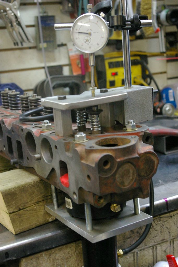
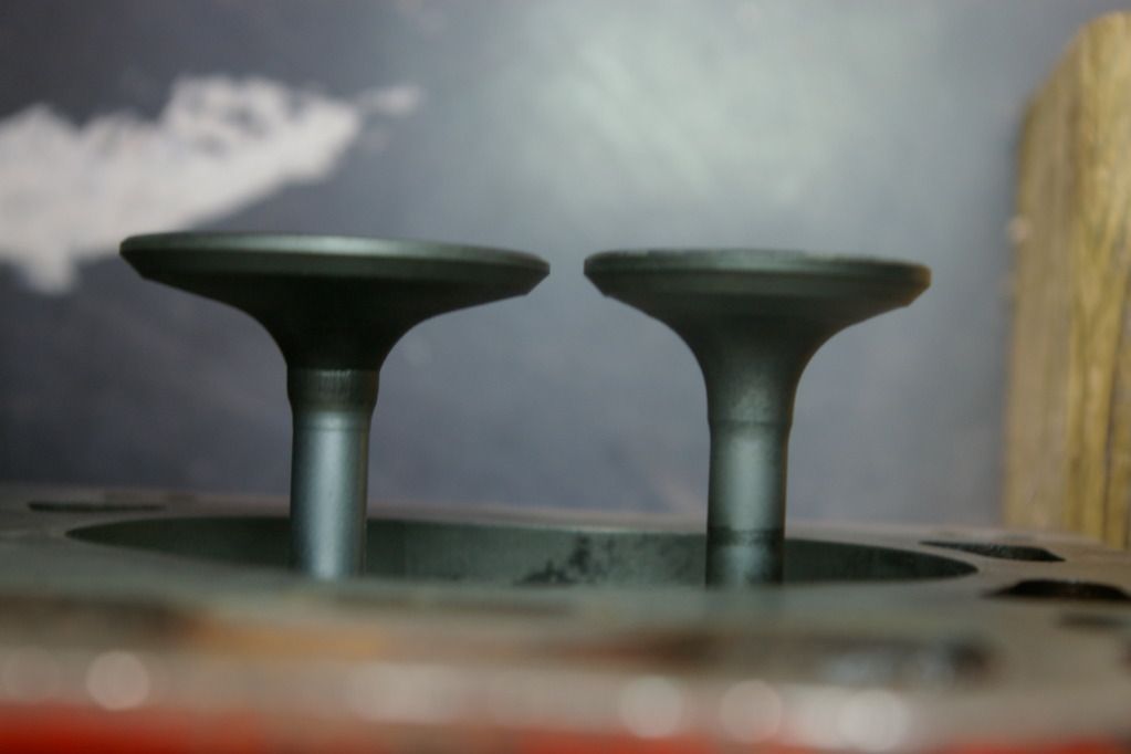
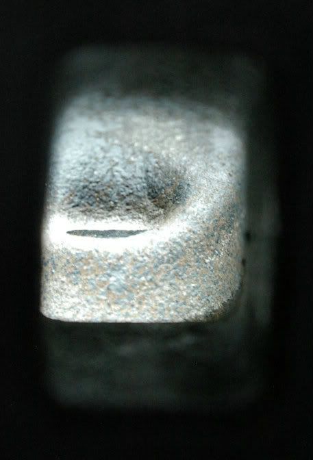
Now for the test - this testing was done with the spare B20F head (1968-1972 - so not the later, better casting) and using the stock valves which look like this (I think they are one piece forgings).
Probing both ports with the manometer varifies that funky things happen around the seat area as reading go from relatively stable to whacky (showing flow disturbances by the seat).
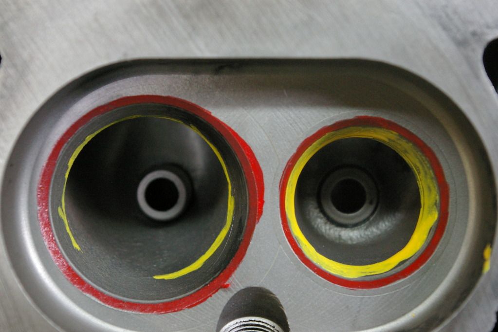
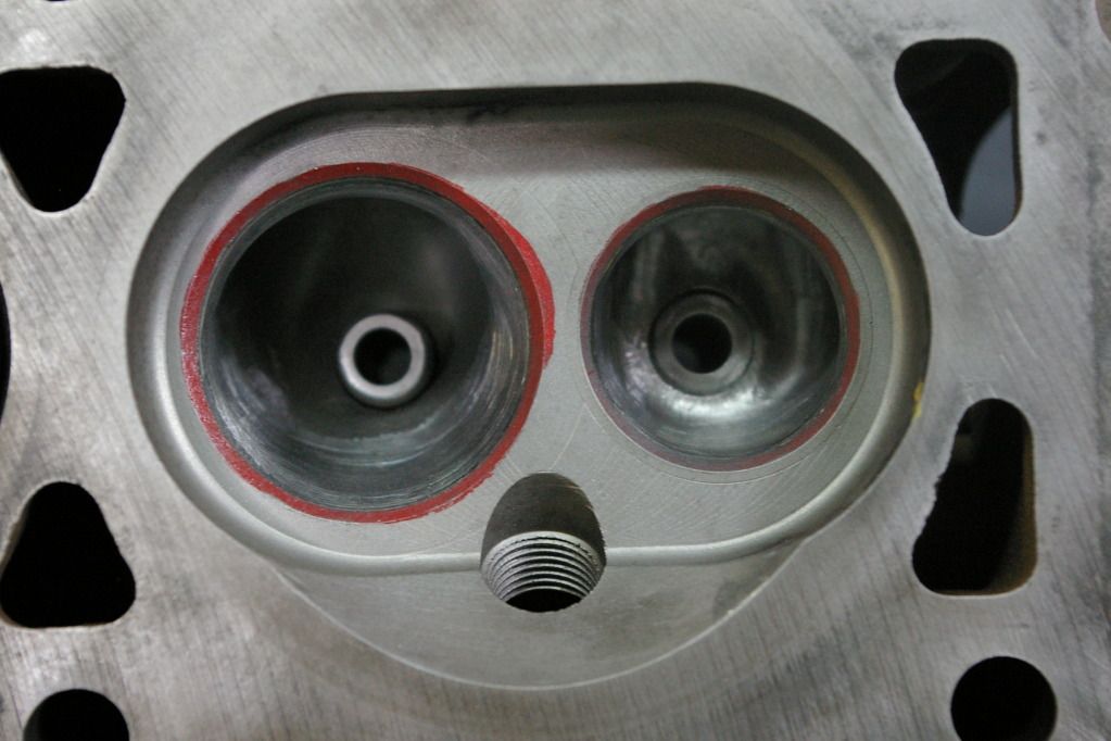
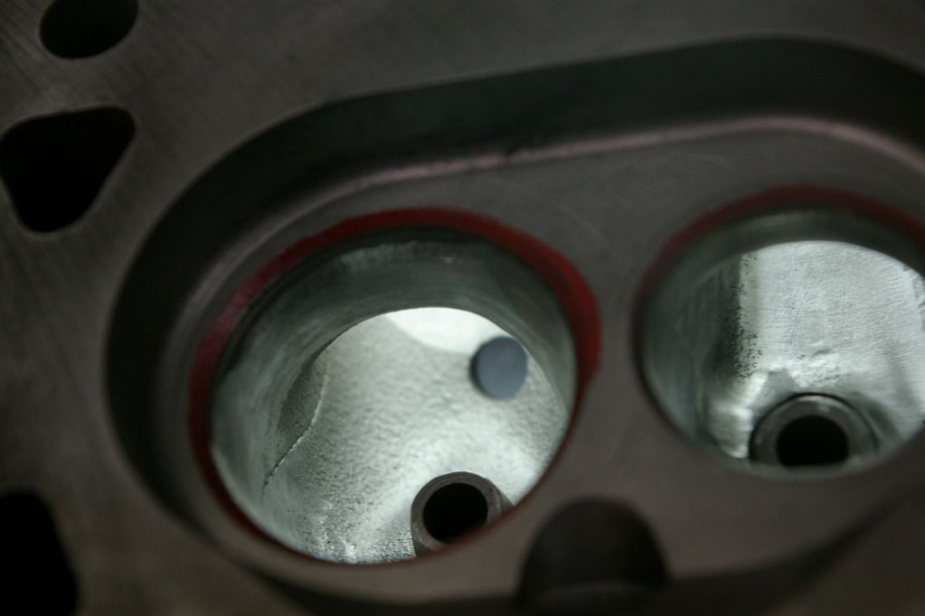
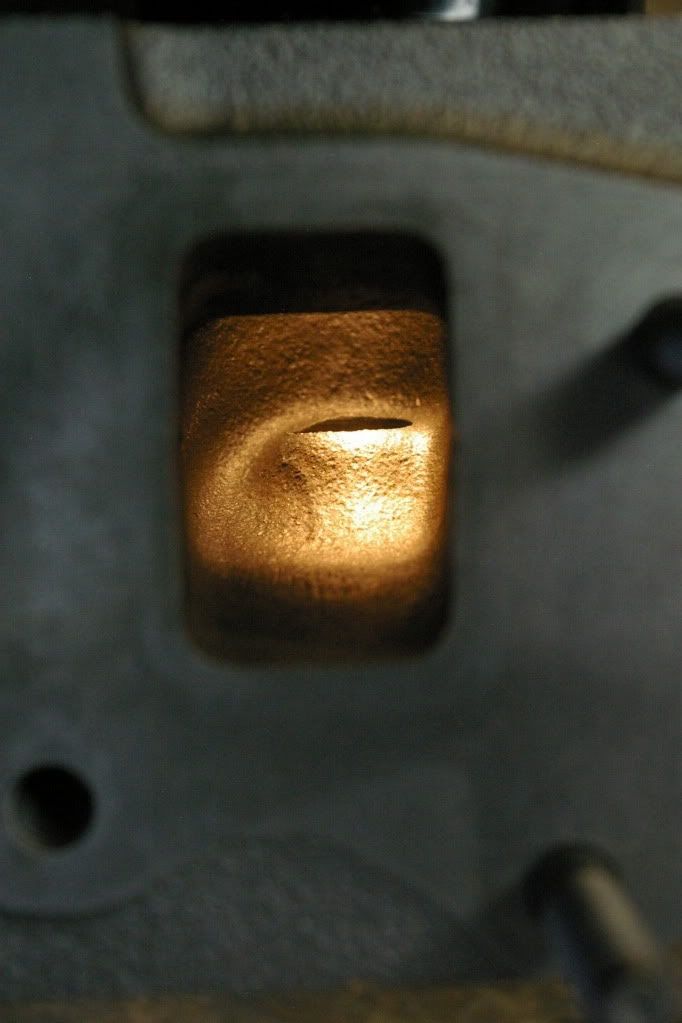
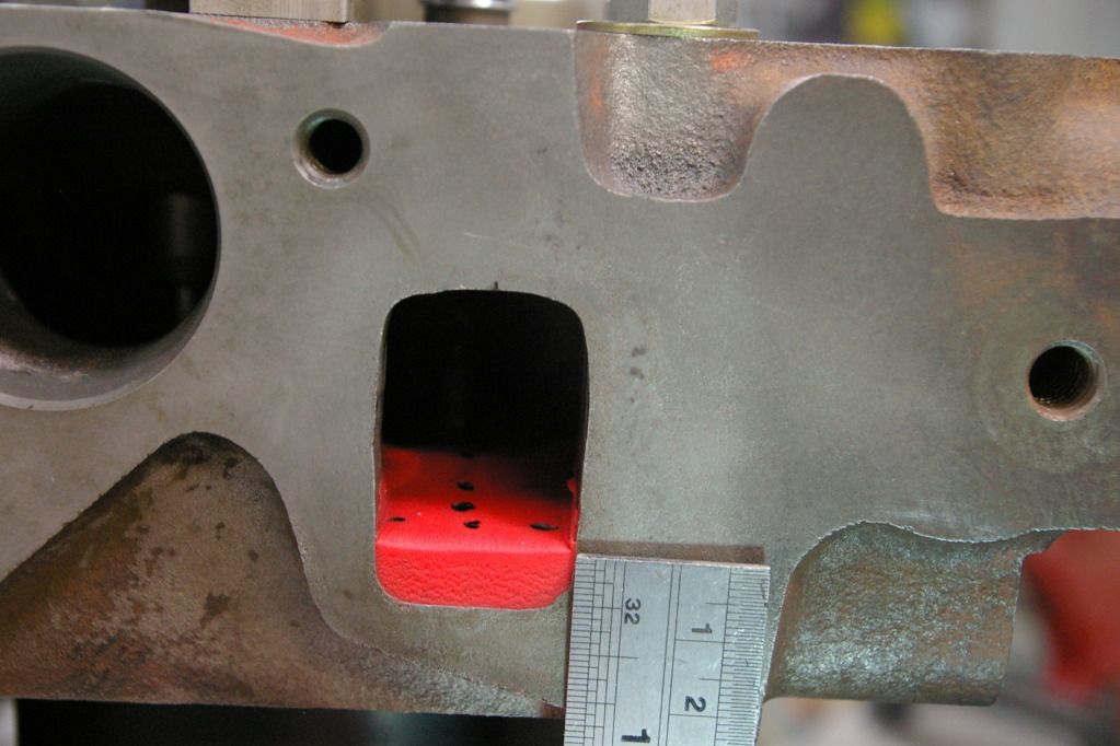
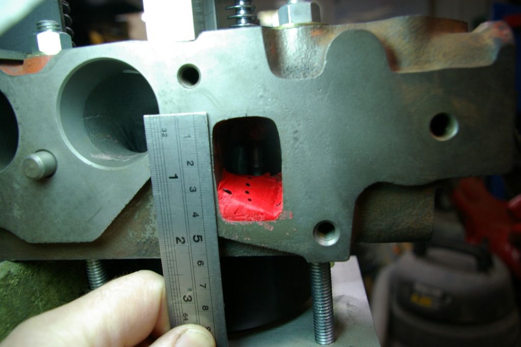
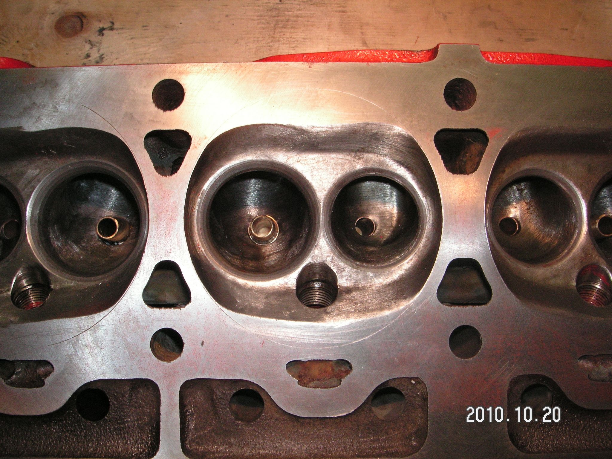
I've posted photo's of these heads before - but this time I've highlighted the area I actually work on. I usually colour the valve seat red to stop me hitting it and the area in yellow is the restriction in the throat. It`s gotta go - so here we are at the start.
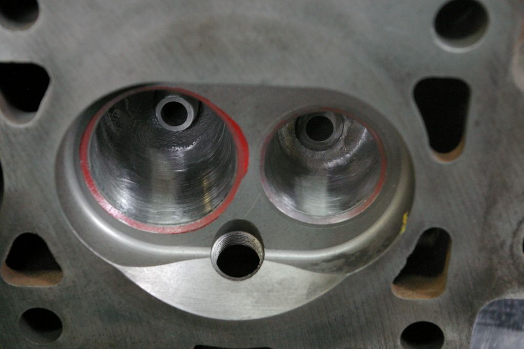
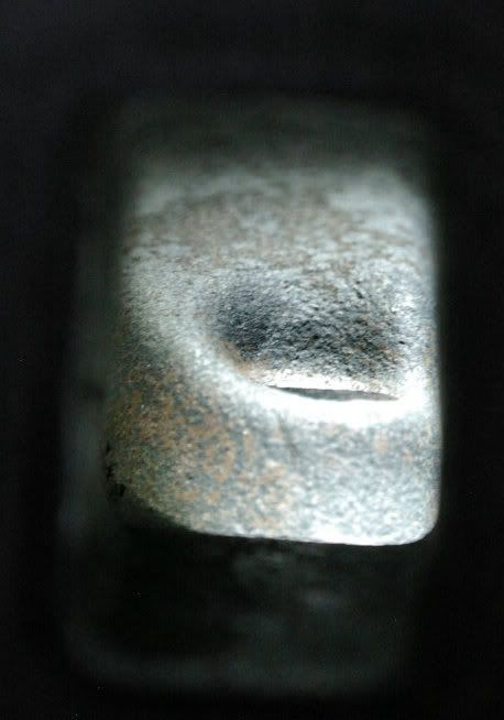
And this is a roughed in port bowl, nothing fancy here at all.
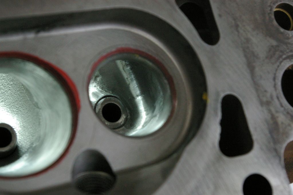
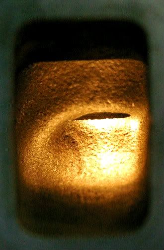
I've taken the back (side away from the port entry/exit) out to the seat as the majority of the intake flow is heading in that direction and the exhaust starts there.
I usually carve around the outside of the valve guide on the exhaust side and accentuate the port roof to complement the bias in the port.
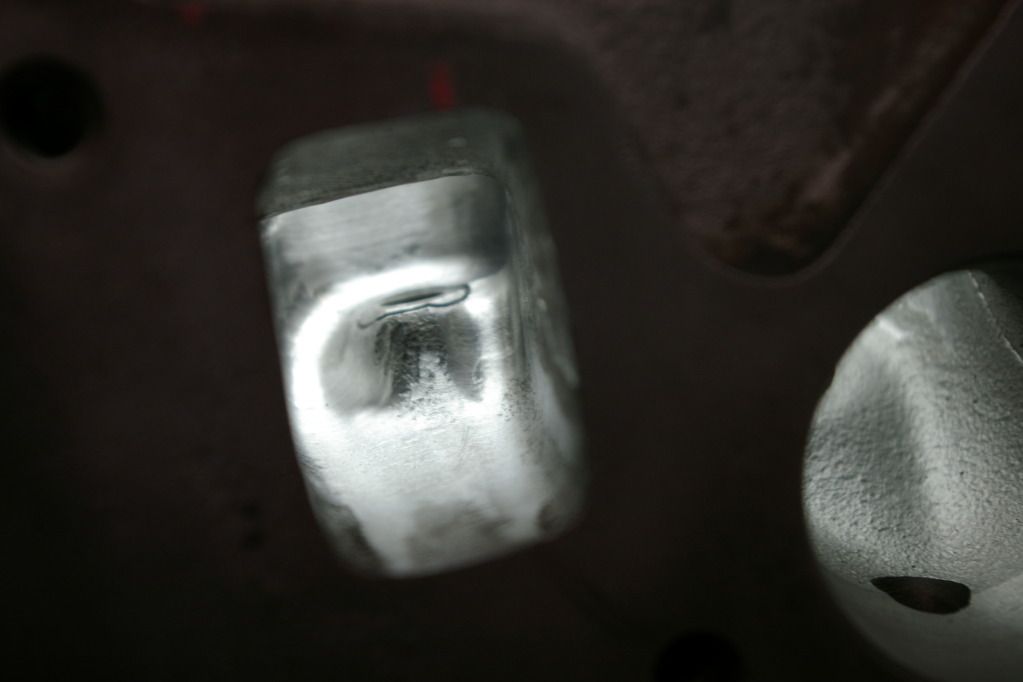
Short-side radius on the intake is cleaned up and profiled, but I try not to make it larger.
Not much to say about the short-side radius on the exhaust side, I just smooth it out and try to keep it from getting sharp.
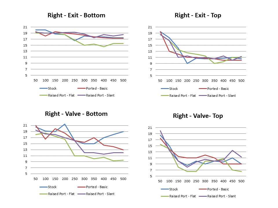
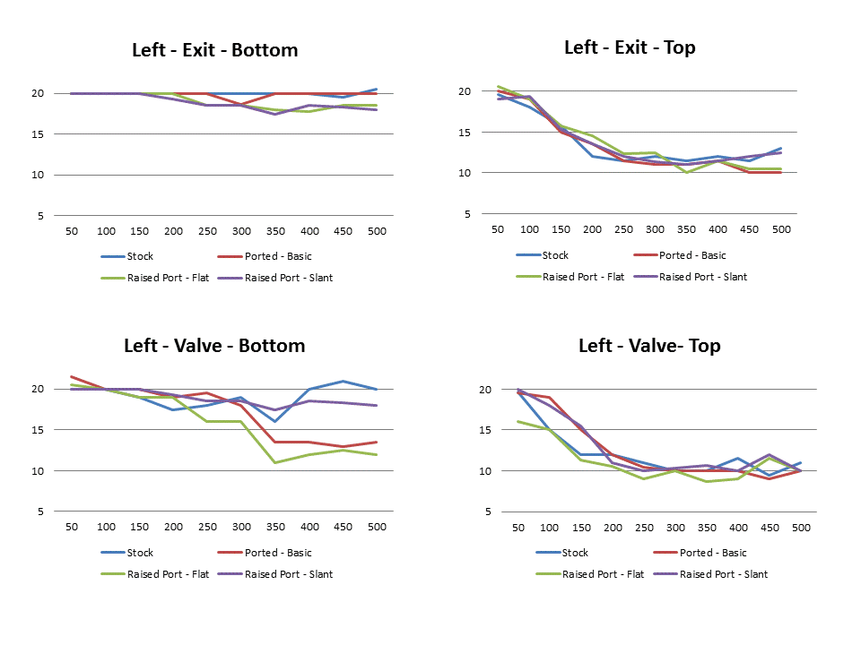
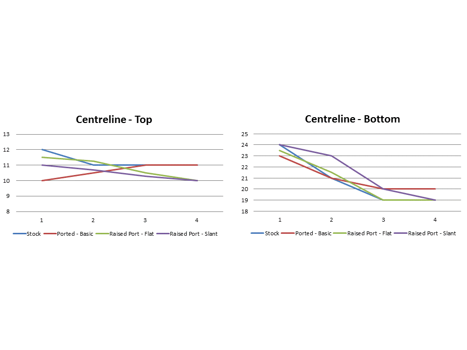
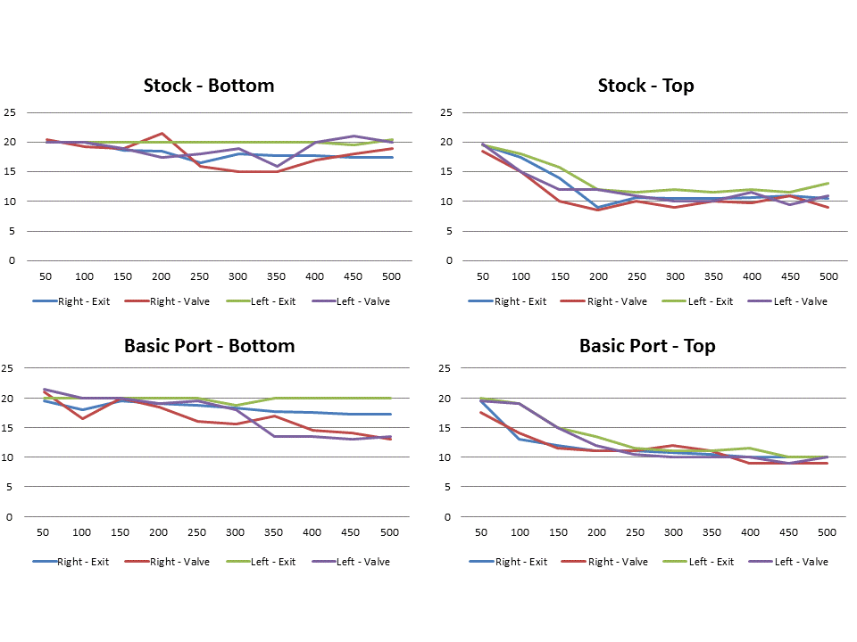
Now for the results (all probe values in inches - start point was a hair over 4" of windex in the tube

) - higher values are worse flow.
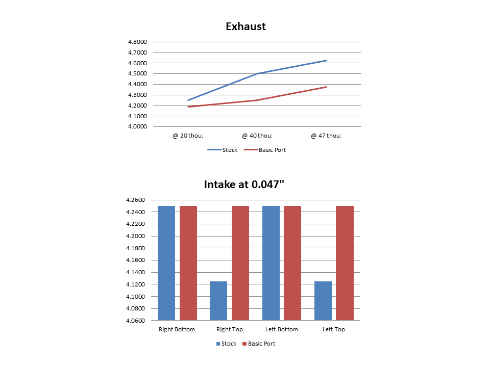
The removal of the exhaust restriction is easy to see as is the improvement in the disribution of flow in the intake. Wish I could give CFM measurements, but it's how not how much I think in this case.
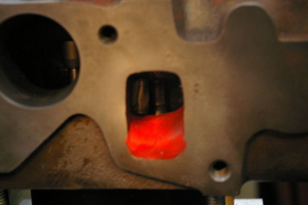
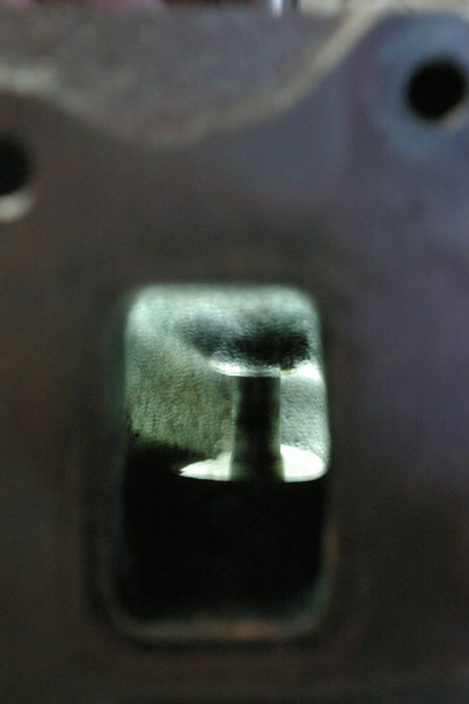
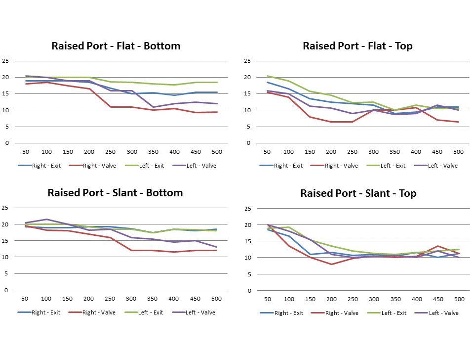
I then played with adding material to the exhaust port floor. I started with building up the port flat.
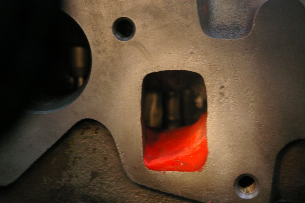
I also tried a slanted floor.
Here are the results.
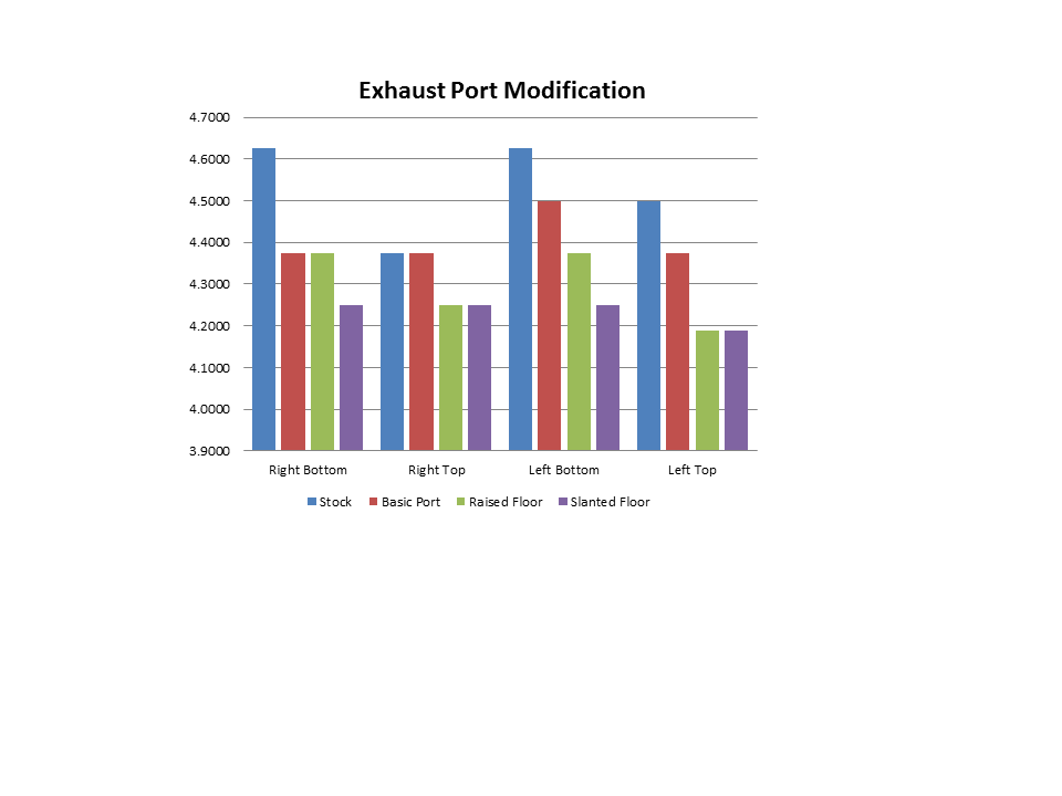
So it appears that the slanted floor works - I can also verify that the distrubution of flow in the port is more even with this port than with a simple raised floor.


