Big update time. Matt came down to lend a much needed helping hand this week. We figure this is worth about a month of me playing in the garage...do settle in for a longish post this time. Really thankful that I was able to get the help with this one.
My rather hopeless goal was to get the frame under my car this week. I cut it out on September long weekend...it's now February and I haven't been able to make a lot of progress with working on other projects. Sometimes it just takes that sort of time for me to work out the engineering that is needed for this job - sometimes I just spend too much time building engines and other junk for people!
So I figured that it would be pretty simple to just toss the cross member in the right position and get the frame built over to it. I had forgotten that the drivers floor does need to come out - but the passenger's side is pretty much done. Well, the cross member turned out to be quite the challenge. We measured it all up and found out that the lower control arm mounts are not perfectly level and they are toed in a little. That's not great, but it's only 1/16", so we decided to not loose sleep over it and get the rack installed.
Now installing the rack I thought would be a piece of cake. My race engineering report told me exactly where to put the rack, so other than locating the pivot accurately, how hard could it be. Here's the original rack that will not be used - note that the tie rod is almost at the frame level.
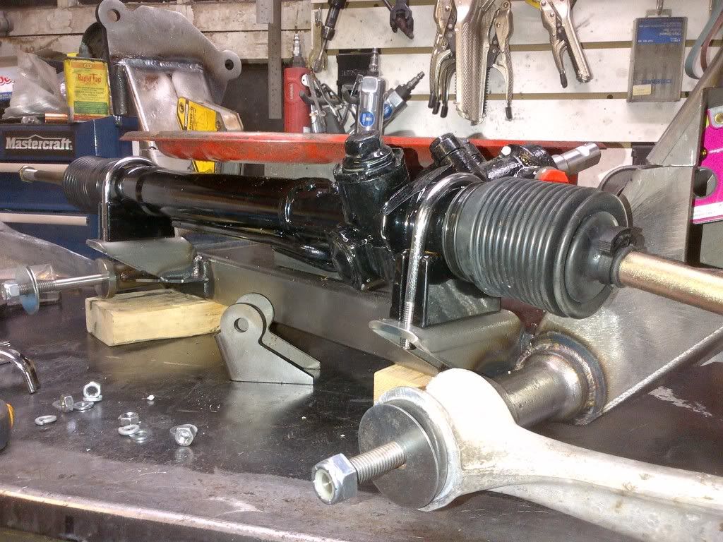
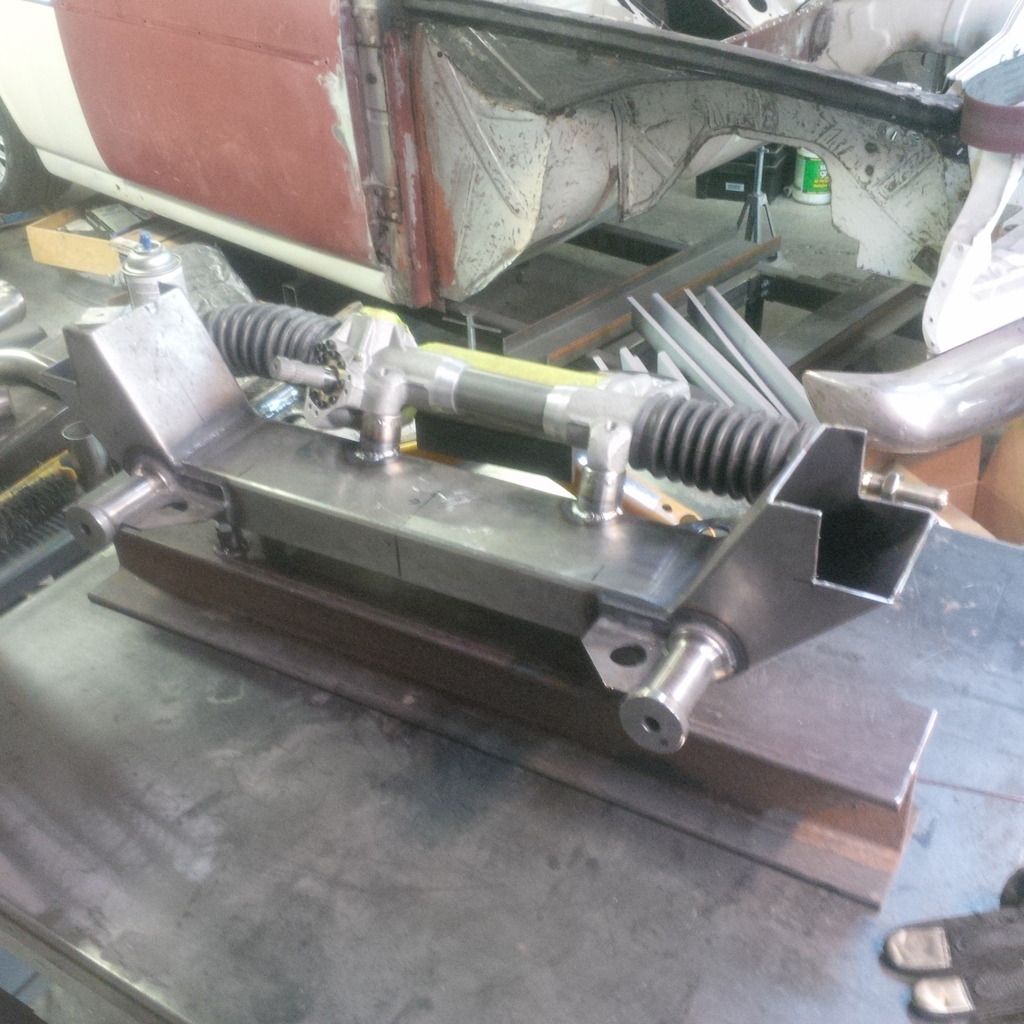
I bought a super-dooper racing rack so I could drop the rack around an inch. This thing is a monster compared to any stock rack I've seen. 2.34 turns lock to lock and a lot of cool options (adjustable road feel and other stuff I don't need). So we work out where it should go based on race engineer Ron Sutton's report.
This is the first attempt - we were 1" too high here based on my foggy memory.
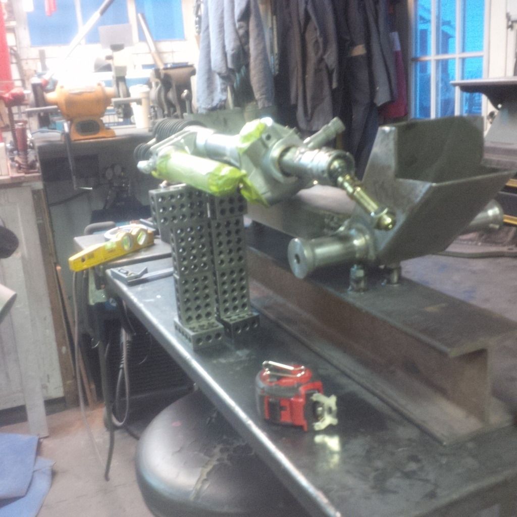
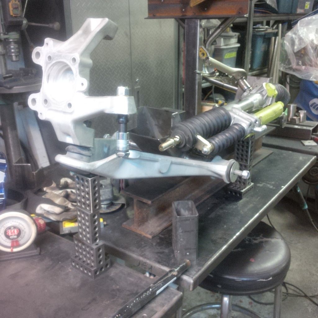
Then we checked clearance at full bump - will that slave cylinder clear the lower control arm?
Yup.
The original way to mount this rack was the way the race guys do it with a simple plate with the two mount holes drilled. Then the plate is angled to take the slave away from pinch points and the thing is welded and trussed up in place. We started to do this and discovered that the long bolts that are needed would hit the cross member. No way to install the plate and install the rack to get optimum Ackerman and the clearance I need for the engine.
We draw out a few ideas on the white board and come up with the idea to toss some tubes through the frame. Tubes through stuff is always cool. Problem is, we don't have a Bridgeport mill and the ability to accurately drill said holes. I've got a drill press, a hole saw and no fear of building stuff. So here we go.
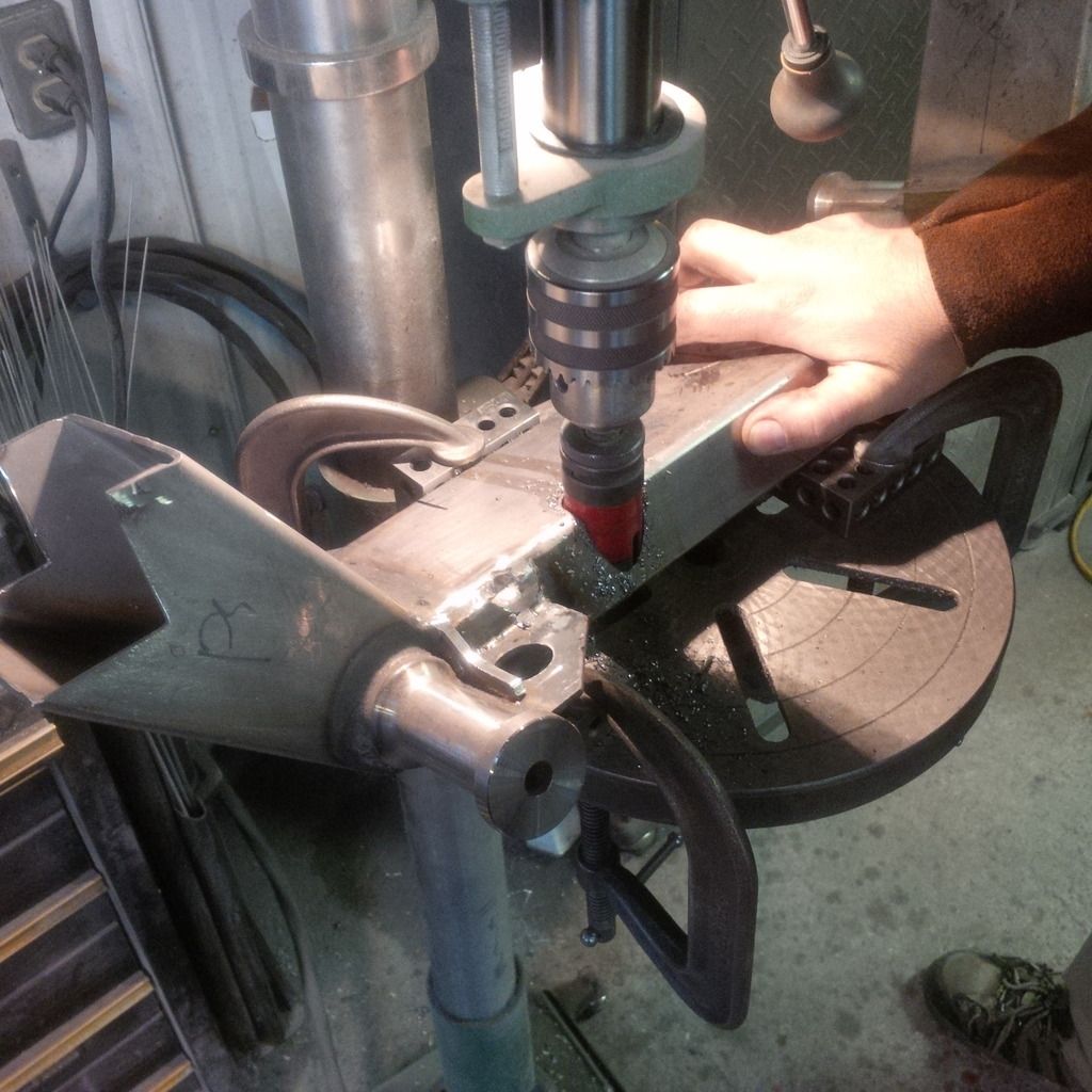
Not perfect, but not garbage either - we guess the two holes are about 1/16 off perfect. I'll take it.
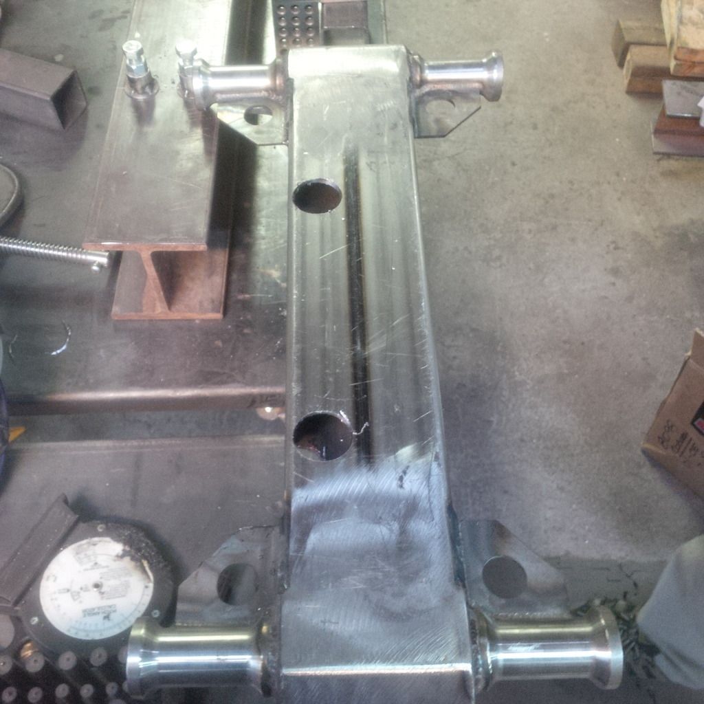
Tubes work like so.
A little while later we have TIG welded tubes with holes that are perfect for the rack and tube stand-offs that are a little imperfect.
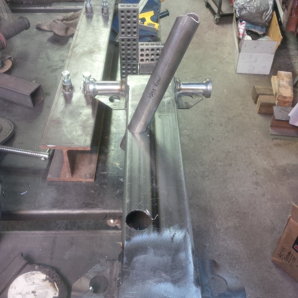
Rack mounted and angles sorted out.
That was a ton of work and thinking and talking it through. Team work was vital.
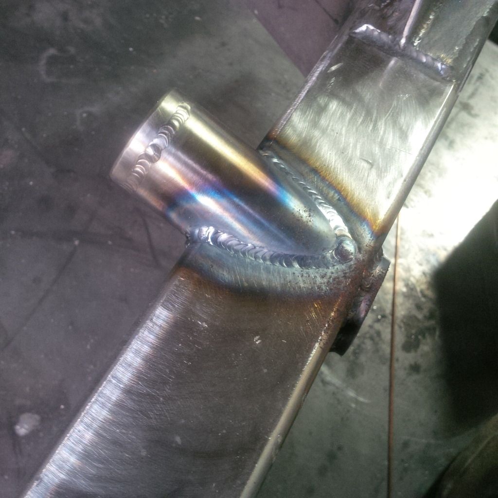
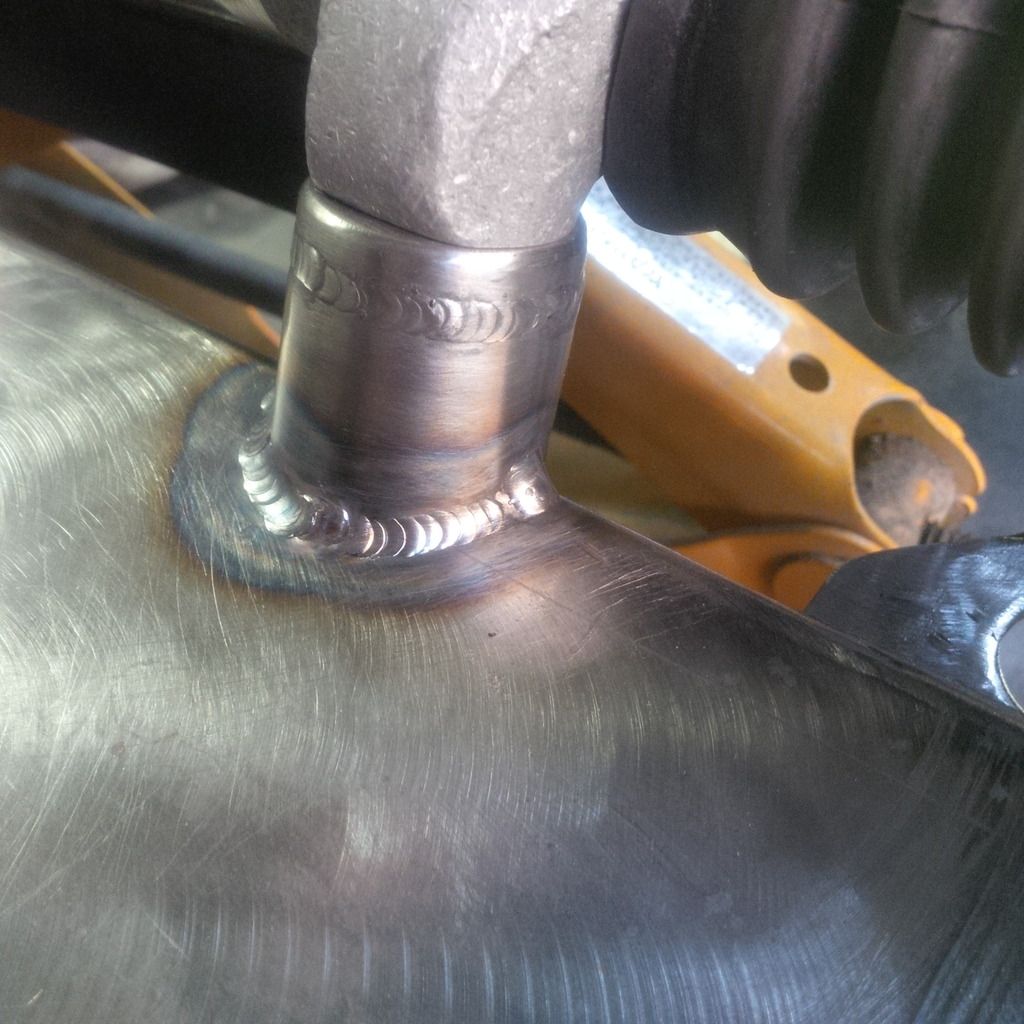
Gratuitous weld picture.
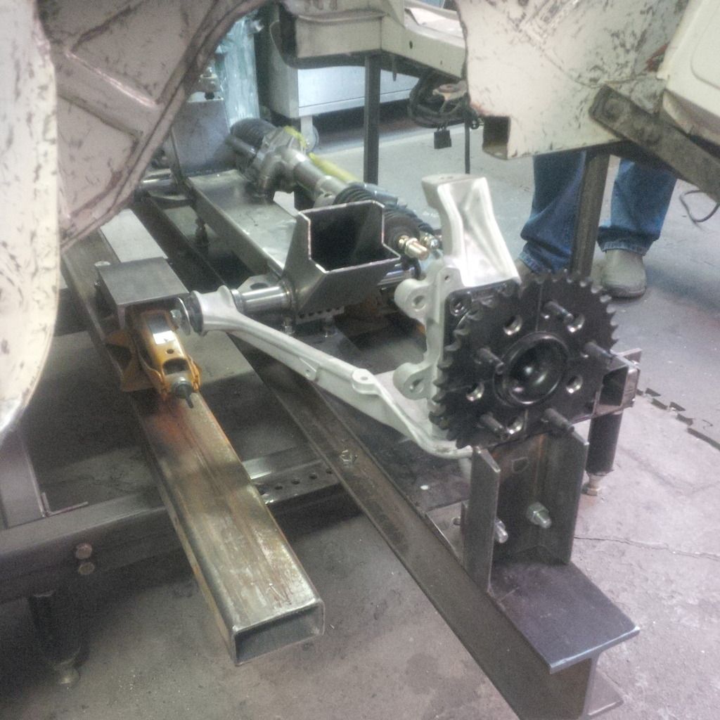
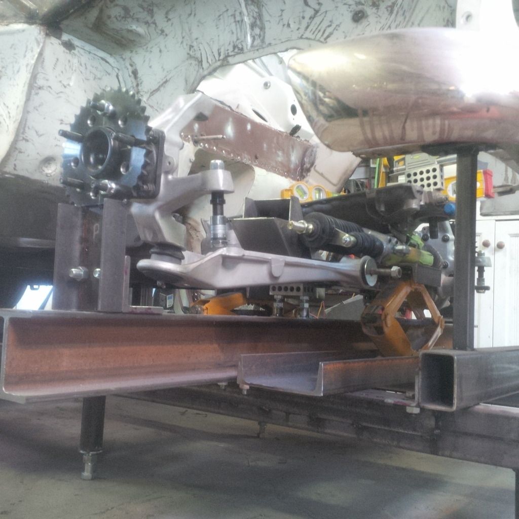
Then we chucked the thing under the car and put some arms on it and uprights and stuff.
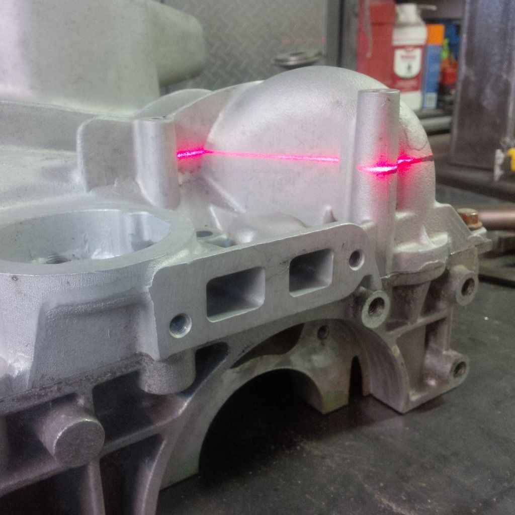
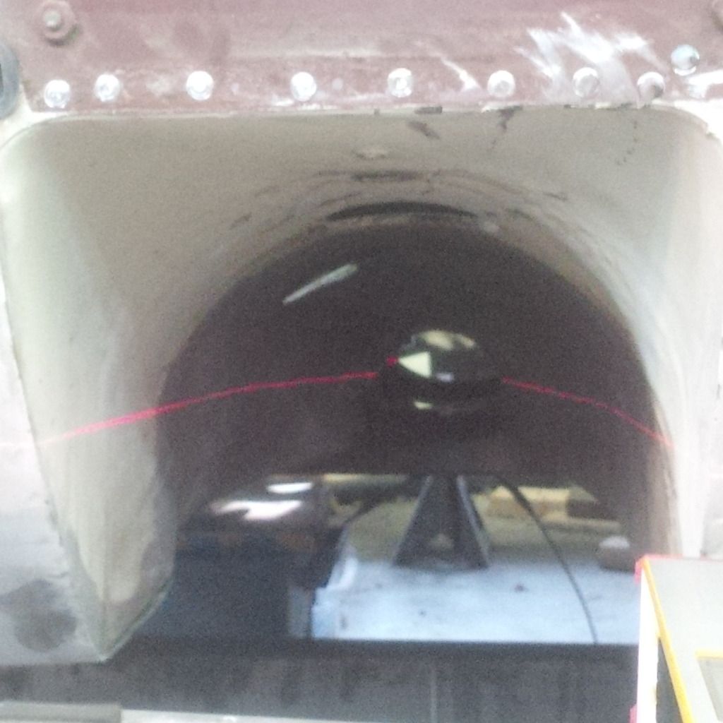
Next up - Frickin laser beams! Note laser line is projected on bottom of the engine intermediate girdle (the pan top) and on the cabinet...perfect at 3".
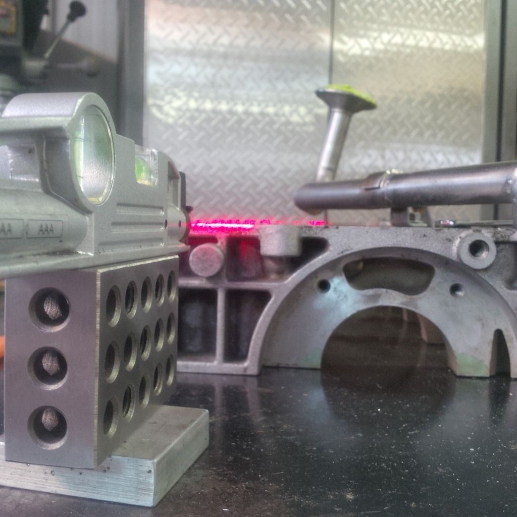
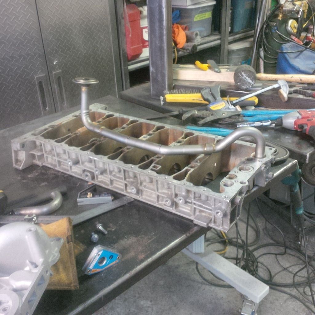
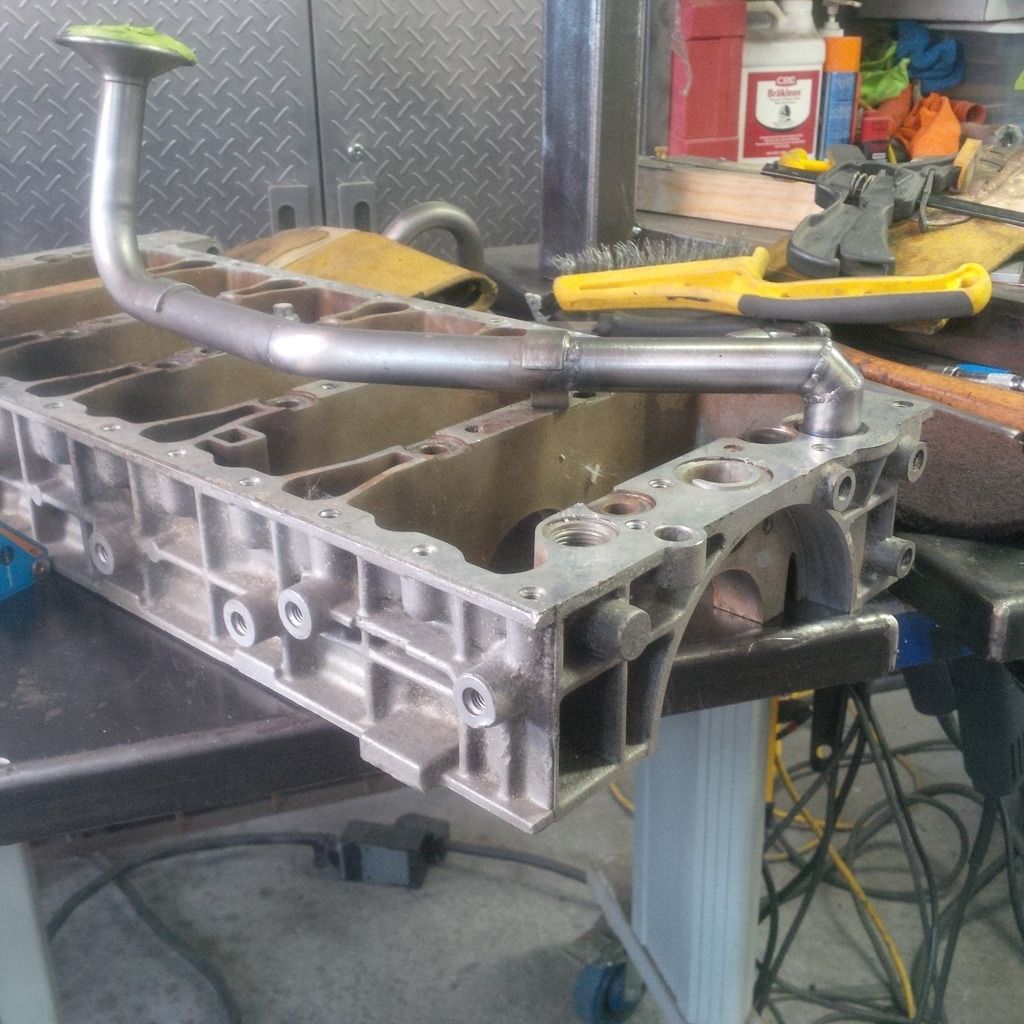
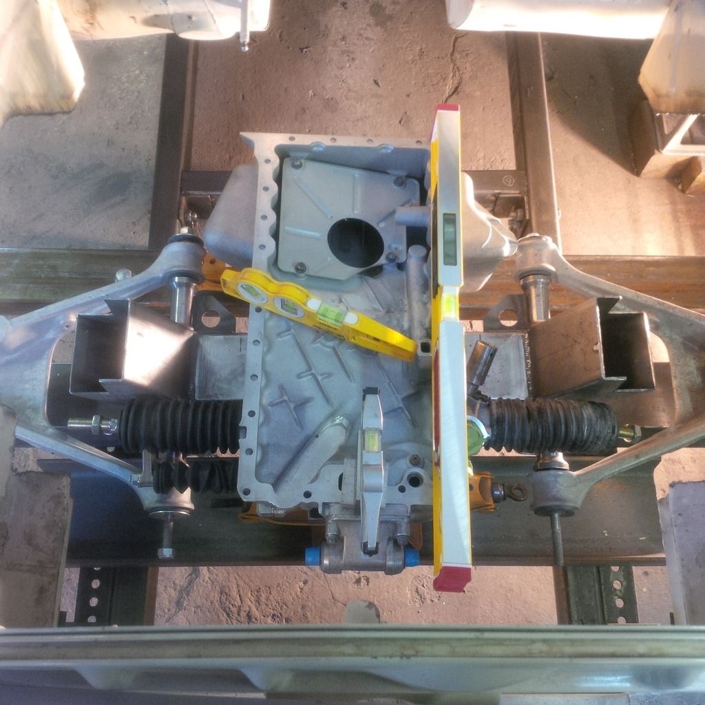
Working out the exact height of the crank shaft centre line. We need this to set the angle of the engine. The stock engine sits at 3 degrees down at the back. I'd like to be as close to this number as possible. We have issues - the pan is not playing nice and the gigantic swan neck feed tube and corresponding swoop in the oil pan are causing almost 8 degrees of tilt to get this to work. That won't do.
So we decide to just cut that stuff off and do it again. I've been working under the assumption that this crank is needed.
Ya, the one going into the front of the pan on your right.
That's the one. I was thinking it would hold a little oil to keep the pump primed. Matt figures it's got nothing to do with that and everything to do with just making the part. Keeping the pan low and bending the tube. If the oil finds it's level like any other fluid and the pump can not hold oil (no reason to believe it would hold pressure when not turning) then with the original tilt towards the rear of the car, the oil would drain out of that tube pretty well. So - off it comes.
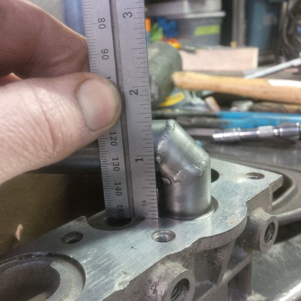
First a few measurements.
Tube is 2 7/8" above the pan and the pan has clearance around it to be a total of 3 3/8" total. If we could loose that it would help.
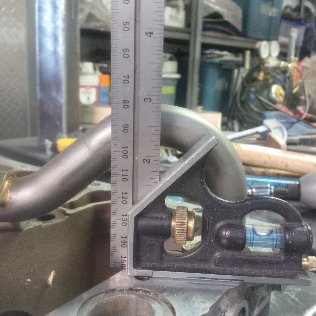
High point on the tube are the clamps - about 1.5" tall. So we could loose 1 3/8" and that's a couple of degrees. At this point I should mention that the tube is metric (22 mm) and I found some in my pile of crap. How random is that. I didn't have to sacrifice my spare pick up tube!
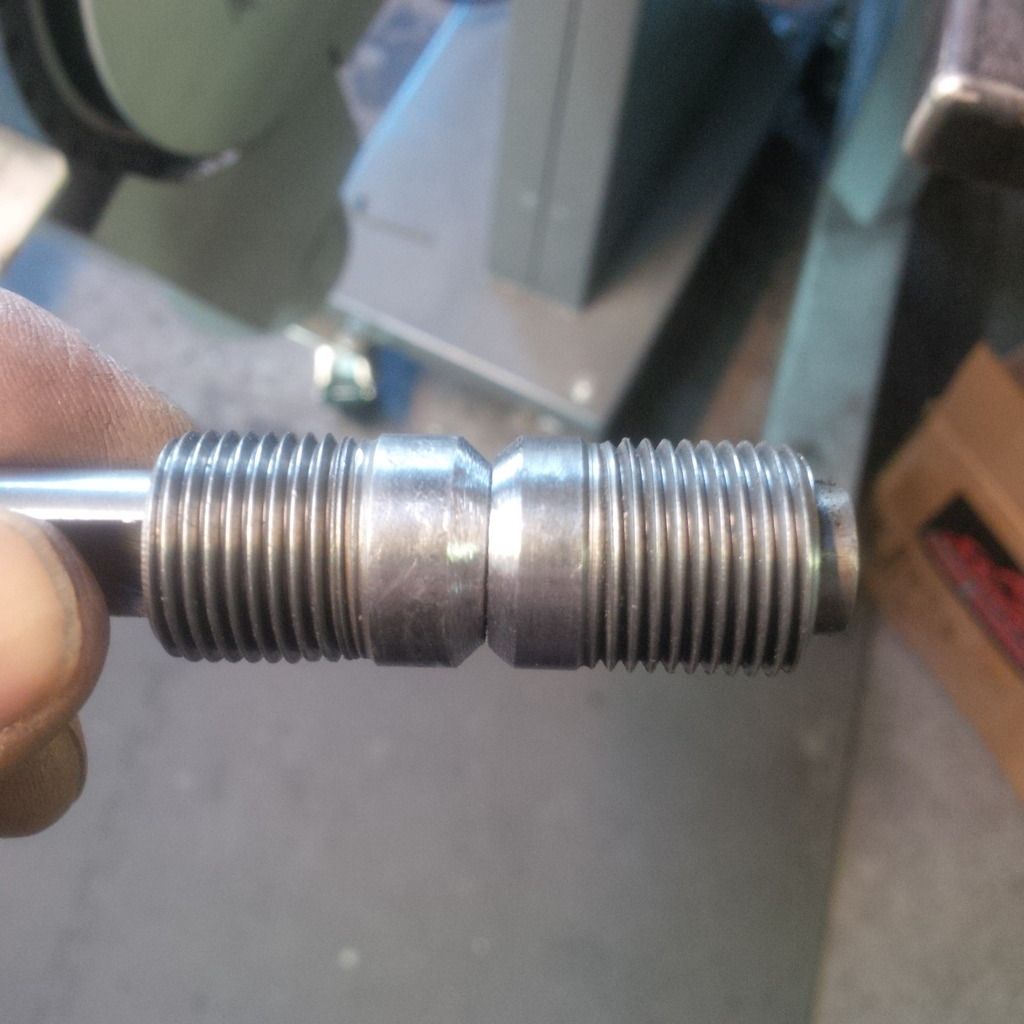
I then made this.
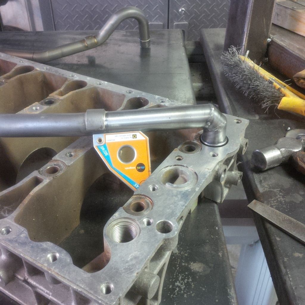
Where is the fit line between these parts?
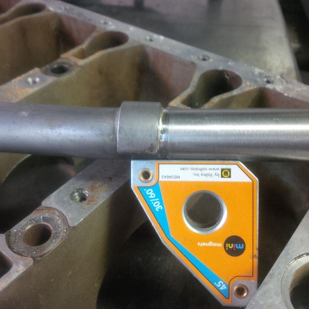
Done.
Doesn't get much better.
Going to loose about this much pan.
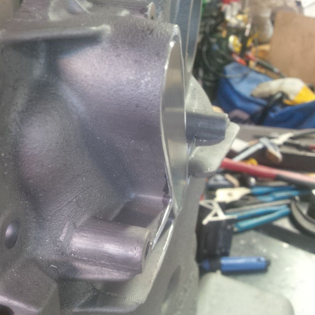
Savagery - cut it out with the little sawsall. That tool is a beast.
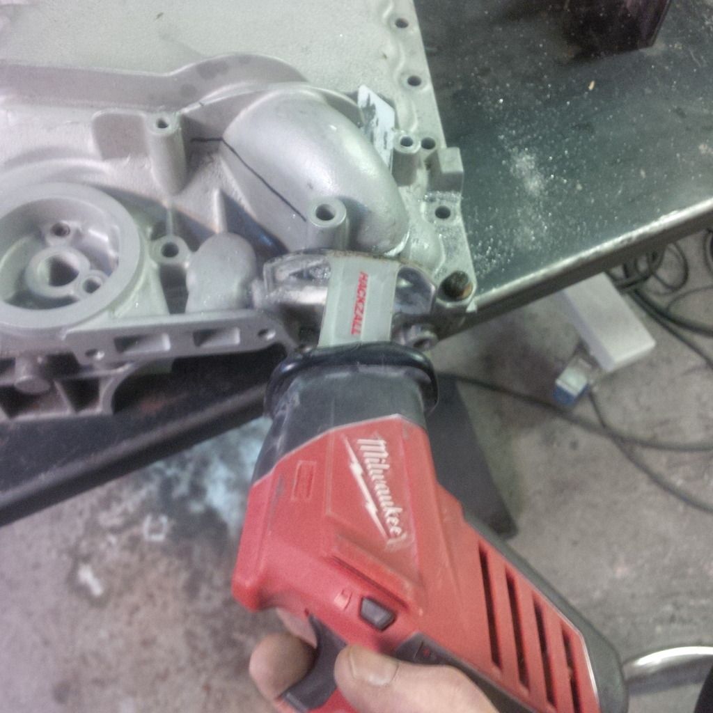
Should have taken the pick-up tube off!
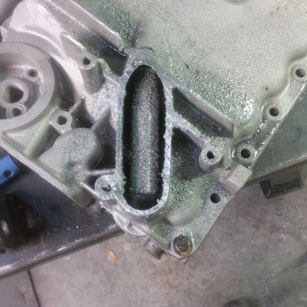
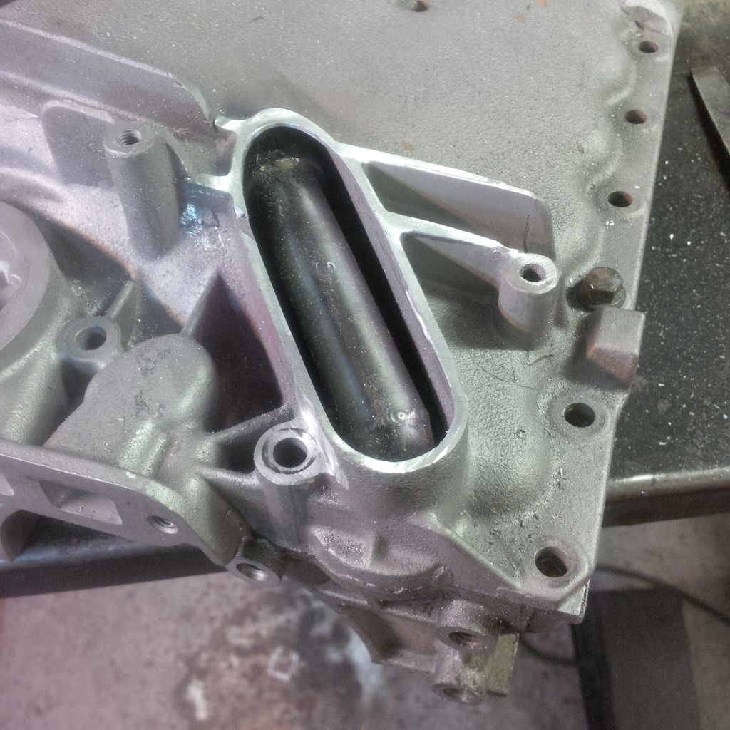
All cleaned out.
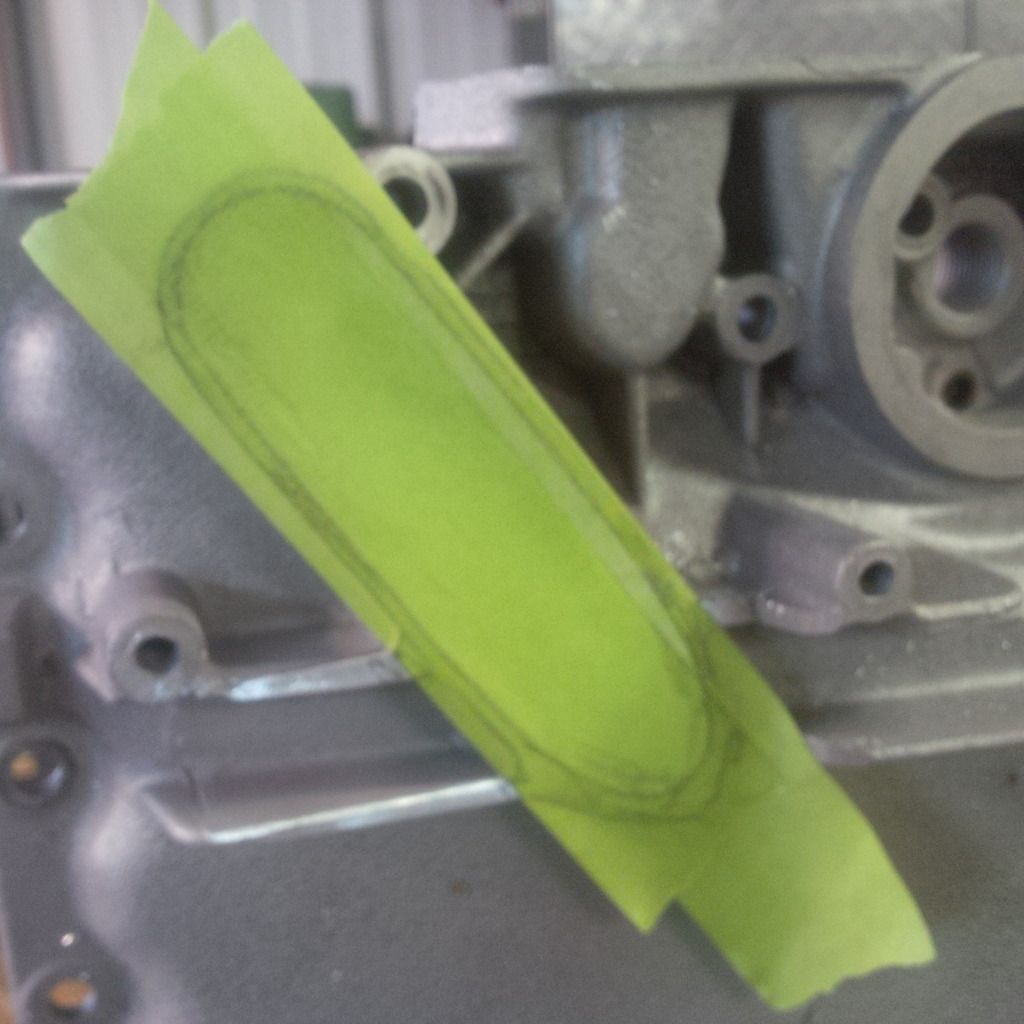
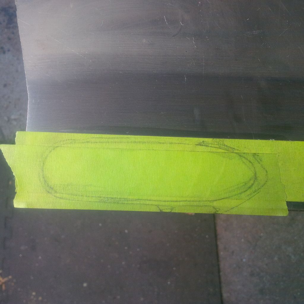
Make a tape pattern.
Put on 6061 plate.
Check fit and file and sand for about 15 minutes to get perfect.
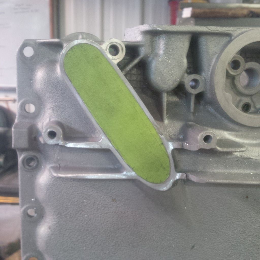
Tight fit - weld prep'ed and ready to go.
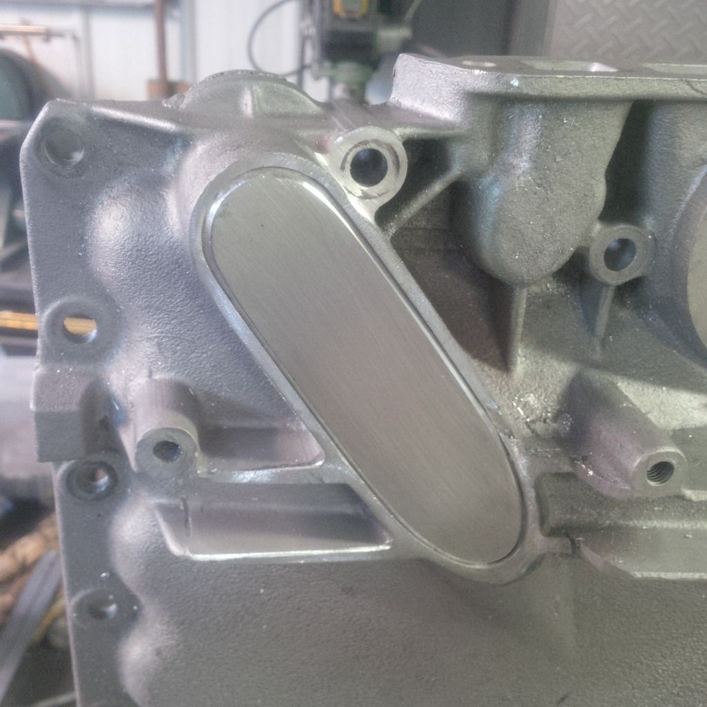
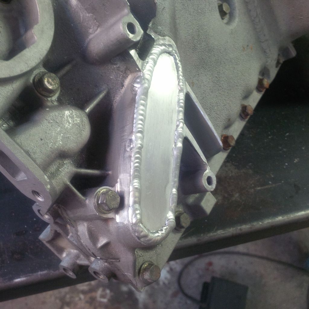
All TIG welded and ready to rock.
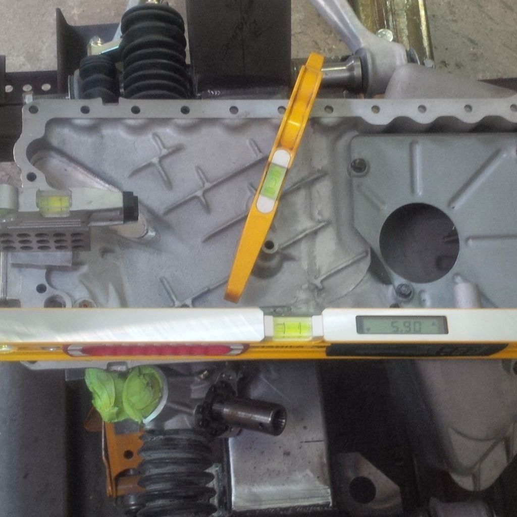
Mocked up again - 5.9 degrees...not bad.
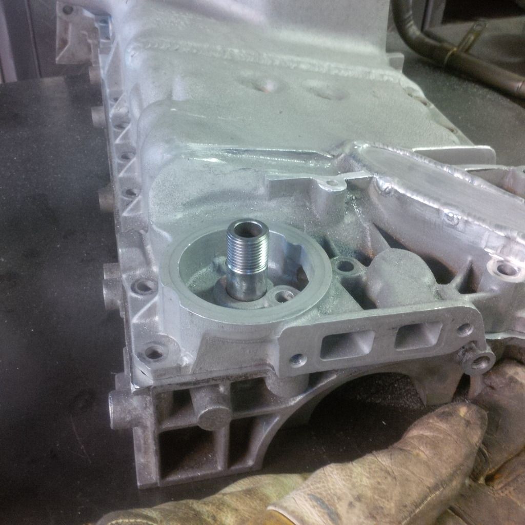
Check the oil filter tube...it's too damn long. Might as well fix that up while I'm at it.
Took 11/16's out of it.
That's better.
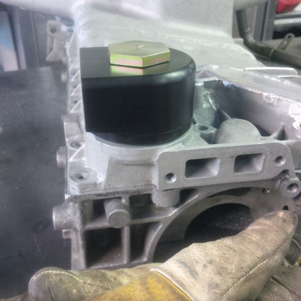
Now my adapter will work - have to make sure it doesn't hit anything.
Now I'm working on the frame. See what happens when you judge things based on Craig time!

That's the middle of the tunnel.
Swan neck fixed pan - loads of clearance now.
It's coming together.
So pleased so far. More to come tomorrow.